Introduction
There are many peripherals that can be added to a microprocessor over the I2C and SPI serial interfaces. These include atmospheric sensors, EEPROMS, and several types of display.
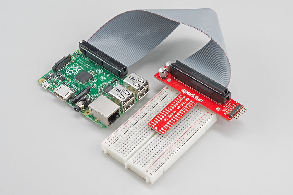
The Pi Wedge helps access the I2C and SPI signals.
This tutorial will walk you through getting the I2C and SPI interfaces of your Raspberry Pi working. These interfaces aren’t enabled by default, and need some extra configuration before you can use them.
Recommended Reading
Before we get started, you might want to review some related background material.
Background & Software Setup
The Raspberry Pi has three types of serial interface on the GPIO header. You’re probably already familiar with the UART serial port, which allows you to open a login session from a serial terminal application, such as PuTTY.
The other two serial interfaces are the Serial Peripheral Interface (SPI) and Inter-Integrated-Circuit bus (I2C). SPI on the Pi allows for up to two attached devices, while I2C potentially allows for many devices, as long as their addresses don’t conflict.
Software Details
The software landscape for the Raspberry Pi has evolved considerably since the introduction of the Pi. Many different operating systems have been ported to the Pi, and the device driver infrastructure has also changed quite a bit.
For this tutorial, we’ll be using a recent version of Raspbian (installed via NOOBS), and the wiringPi I/O library.
With the implementation of device tree overlays in Raspbian, some of the specific interface enablement details have changed. If you’re working with an older install, it might be worth backing up your SD card, and starting with a fresh install.
OS and Library Install
If you’re starting from scratch, with a blank SD card, you’ll want to install Raspbian. If you’ve already got a working Raspbian system, skip ahead to step 3.
- Download the NOOBS image. As of this writing, it’s at version 1.4.2.
- Follow the official installation instructions.
- Follow the Wiring Pi Instructions to get git, update and upgrade your Rasbpian packages, then install WwiringPi.
Be patient – each of these steps takes a while.
Once you’ve got wiringPi installed, run the
gpio commands shown below.>gpio -v >gpio readall
It should respond with some information about the wiringPi version and the Pi that its running on, then draw a table illustrating the configuration for the pins in the 40-pin connector.
The I2C and SPI interfaces each require some additional configuration and initialization, which we’ll cover in later sections.
Connecting To The Ports
Before we get into the configuration and software examples, lets locate the pins used by each of these interfaces.
If you’re directly connecting to the pins on the Pi, they’re a little disorganized. I2C.1 is near one end, while SPI and I2C.0 are in the middle of the header. If you’re connecting to these pins, be sure to count carefully.
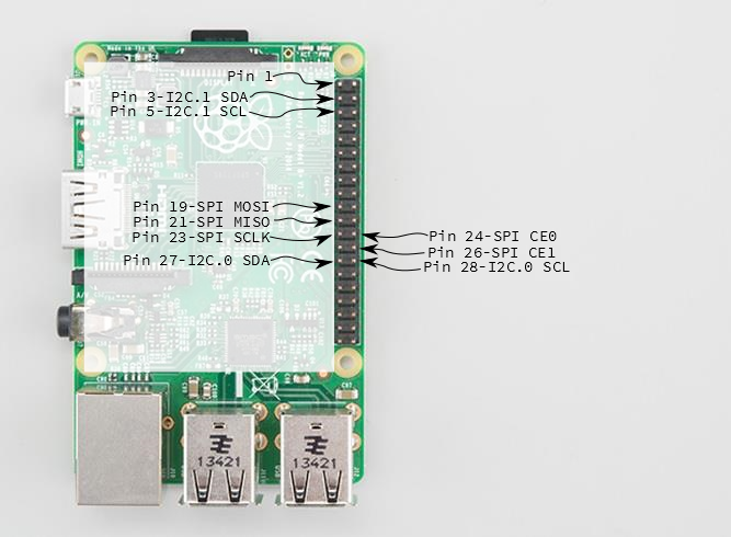
Pi Serial Bus Pins
The Pi Wedge adapter PCB rearranges the pins, and labels them clearly. We’ll be using the Wedge for the following examples.
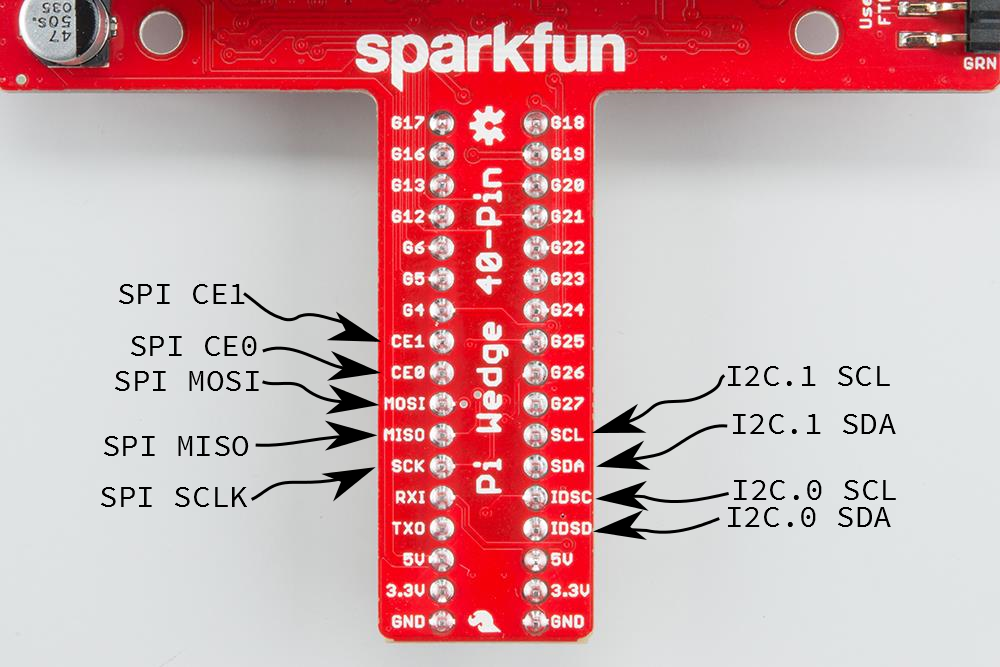
Wedge Serial Bus Pins
SPI on Pi
Configuration
The SPI peripheral is not turned on by default. To enable it, do the following.
- Run
sudo raspi-config. - Use the down arrow to select
9 Advanced Options - Arrow down to
A6 SPI. - Select
yeswhen it asks you to enable SPI, - Also select
yeswhen it asks about automatically loading the kernel module. - Use the right arrow to select the
<Finish>button. - Select
yeswhen it asks to reboot.

Raspi-config for SPI
The system will reboot. When it comes back up, log in and enter the following command
>ls /dev/*spi*
The Pi should respond with
/dev/spidev0.0 /dev/spidev0.1
These represent SPI devices on chip enable pins 0 and 1, respectively. These pins are hardwired within the Pi. Ordinarily, this means the interface supports at most two peripherals, but there are cases where multiple devices can be daisy-chained, sharing a single chip enable signal.
Programming Example
Required Materials
- The 40-pin Pi Wedge.
- A Raspberry Pi B+ or Pi 2 Model B single board computer.
- A Solderless Breadboard.
- Some jumper wires.
- A Serial 7-Segment display.
The Serial 7-Segment display is particularly useful for testing serial interfaces, because it can accept command from a UART, SPI, or I2C.
Connections
The display was connected to the Pi, via the Pi Wedge, as follows.
| Rabpberry Pi Signal | Serial 7-seg Signal |
| GND | GND |
| 3.3V | VCC |
| CE1 | SS (Shift Select) |
| SCK | SCK |
| MOSI | SDI |
| MISO | SDO |
The test hardware looked like this.

Serial 7-Segment connections for SPI
Sample Program
/****************************************************************************** i2ctest.cpp Raspberry Pi I2C interface demo Byron Jacquot @ SparkFun Electronics> 4/2/2014 https://github.com/sparkfun/Pi_Wedge A brief demonstration of the Raspberry Pi I2C interface, using the SparkFun Pi Wedge breakout board. Resources: This example makes use of the Wiring Pi library, which streamlines the interface to the the I/O pins on the Raspberry Pi, providing an API that is similar to the Arduino. You can learn about installing Wiring Pi here: http://wiringpi.com/download-and-install/ The wiringPi SPI API is documented here: https://projects.drogon.net/raspberry-pi/wiringpi/spi-library/ The init call returns a standard file descriptor. More detailed configuration of the interface can be performed using ioctl calls on that descriptor. See the wiringPi SPI implementation (wiringPi/wiringPiSPI.c) for some examples. Parameters configurable with ioctl are documented here: http://git.kernel.org/cgit/linux/kernel/git/torvalds/linux.git/tree/Documentation/spi/spidev Hardware connections: This file interfaces with the SparkFun Serial 7 Segment display: https://www.sparkfun.com/products/11629 The board was connected as follows: (Raspberry Pi)(Serial 7 Segment) GND -> GND 3.3V -> Vcc CE1 -> SS (Shift Select) SCK -> SCK MOSI -> SDI MISO -> SDO To build this file, I use the command: > g++ spitest.cpp -lwiringPi Then to run it, first the spi kernel module needs to be loaded. This can be done using the GPIO utility. > gpio load spi > ./a.out This test uses the single-segment mode of the 7 segment display. It shifts a bit through the display characters, lighting a single character of each at a time. Development environment specifics: Tested on Raspberry Pi V2 hardware, running Raspbian. Building with GCC 4.6.3 (Debian 4.6.3-14+rpi1) This code is beerware; if you see me (or any other SparkFun employee) at the local, and you've found our code helpful, please buy us a round! Distributed as-is; no warranty is given. ******************************************************************************/ #include <iostream> #include <errno.h> #include <wiringPiSPI.h> #include <unistd.h> using namespace std; // channel is the wiringPi name for the chip select (or chip enable) pin. // Set this to 0 or 1, depending on how it's connected. static const int CHANNEL = 1; int main() { int fd, result; unsigned char buffer[100]; cout << "Initializing" << endl ; // Configure the interface. // CHANNEL insicates chip select, // 500000 indicates bus speed. fd = wiringPiSPISetup(CHANNEL, 500000); cout << "Init result: " << fd << endl; // clear display buffer[0] = 0x76; wiringPiSPIDataRW(CHANNEL, buffer, 1); sleep(5); // Do a one-hot bit selection for each field of the display // It displays gibberish, but tells us that we're correctly addressing all // of the segments. for(int i = 1; i <= 0x7f; i <<= 1) { // the decimals, colon and apostrophe dots buffer[0] = 0x77; buffer[1] = i; result = wiringPiSPIDataRW(CHANNEL, buffer, 2); // The first character buffer[0] = 0x7b; buffer[1] = i; result = wiringPiSPIDataRW(CHANNEL, buffer, 2); // The second character buffer[0] = 0x7c; buffer[1] = i; result = wiringPiSPIDataRW(CHANNEL, buffer, 2); // The third character buffer[0] = 0x7d; buffer[1] = i; result = wiringPiSPIDataRW(CHANNEL, buffer, 2); // The last character buffer[0] = 0x7e; buffer[1] = i; result = wiringPiSPIDataRW(CHANNEL, buffer, 2); // Pause so we can see them sleep(5); } // clear display again buffer[0] = 0x76; wiringPiSPIDataRW(CHANNEL, buffer, 1); }
When you built wiringPi, you might have noticed the statement about how to compile applications against it.
NOTE: To compile programs with wiringPi, you need to add: -lwiringPi to your compile line(s) To use the Gertboard, MaxDetect, etc. code (the devLib), you need to also add: -lwiringPiDev to your compile line(s).
Thus, we compile using the command.
>g++ spitest.cpp -lwiringPi -o spitest
Which generates an executable
spitest. When we run ./spitest, it will exercise each of the segments of the display. It illuminates a segment in each digit for 5 seconds, before moving to the next segment. It takes about 40 seconds overall.