The Internet of Things on AWS:
Connectivity is a key element to evaluate when designing IoT systems as it will weigh heavily on the performance, capabilities, autonomy of battery powered objects, and cost of the overall solution. There is no one network that fits all scenarios which is why AWS partners with many different network providers. By partnering, you can then choose the most relevant network to satisfy your business requirements. In this blog post, we’ll explore providing LPWAN connectivity to your objects using the Sigfox network. Pierre Coquentin (Sigfox – Software Architect) will explain what Sigfox is and how to connect objects while Jean-Paul Huon (Z#bre – CTO) will share his experience using Sigfox with AWS in production.
Why Sigfox?
Sigfox provides global, simple, cost-effective, and energy-efficient solutions to power the Internet of Things (IoT). Today, Sigfox’s worldwide network and broad ecosystem of partners are already enabling companies to accelerate digital transformation and to develop new services and value.In order to connect devices to its global network, Sigfox uses an ultra-narrow-band (UNB) radio technology. The technology is key to providing a scalable, high-capacity network with very low energy consumption, while maintaining a light and easy-to-rollout infrastructure. The company operates in the ISM bands (license-free frequency bands), on the 902MHz band in the U.S., as well as the 868MHz band in Europe.
Once devices are connected to the Sigfox network, data can be transmitted to AWS IoT, enabling customers to create IoT applications that deliver insight into and the ability to act upon their data in real-time.
Please find more information at https://www.sigfox.com/
Send data from Sigfox to AWS IoT
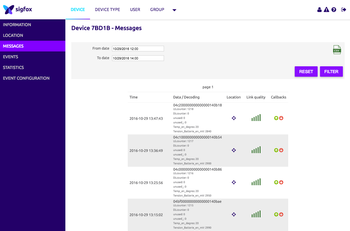
We’ll start from the assumption that you already have objects connected and sending data to the Sigfox network. All that is left to do, is to configure the native AWS IoT connector to push your data to the AWS Cloud. To make things a bit more interesting, we will store all the data sent by your devices in an Amazon DynamoDB table.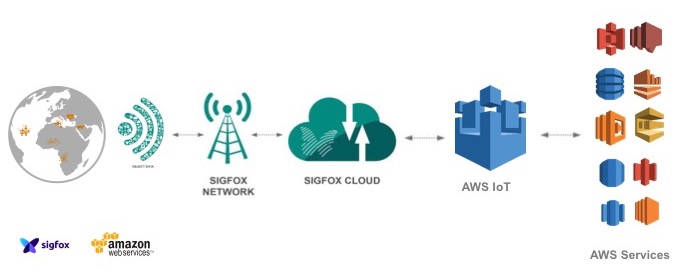
In order to implement this architecture, we are going to perform the following steps:
- Configure the AWS IoT Connector in the Sigfox Console
- Provision the necessary resources on AWS so Sigfox can send data into your AWS account securely through the AWS IoT connector using a CloudFormation script that will generate IAM roles and permissions.
- Manually create a rule in AWS IoT and a DynamoDB table so we can store the data coming from Sigfox into the DynamoDB table
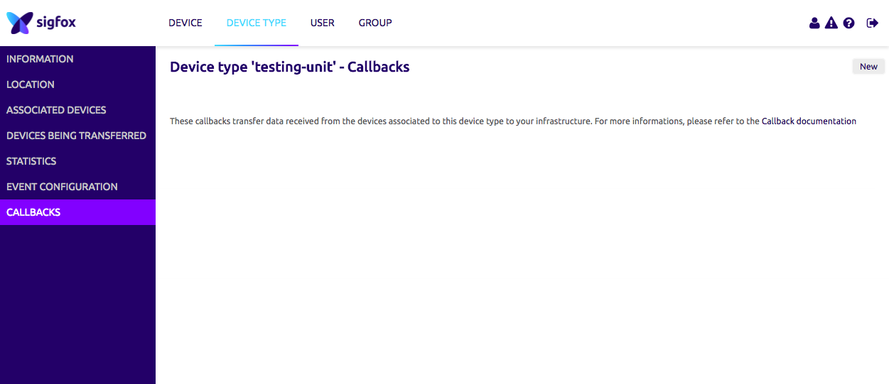
First, log into the Sigfox console, go to the “Callbacks” section and click on the “New” button to create a new “Callback”.
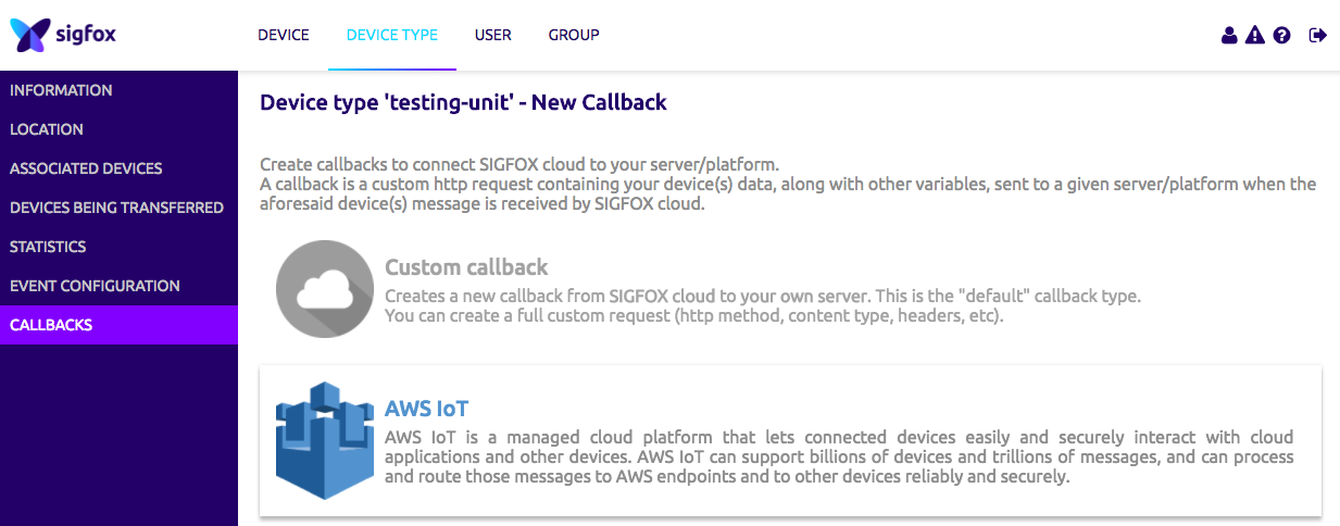
Now select the “AWS IoT” option as the type of “Callback”.
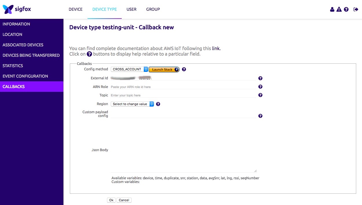
Please copy the “External Id” given to you in your clipboard, it will be useful later. The “External Id” is unique to your account and enables greater security when authorizing third party to access your AWS resources, you can find more information here.
Next click on “Launch Stack” and leave the “CROSS_ACCOUNT” option selected.
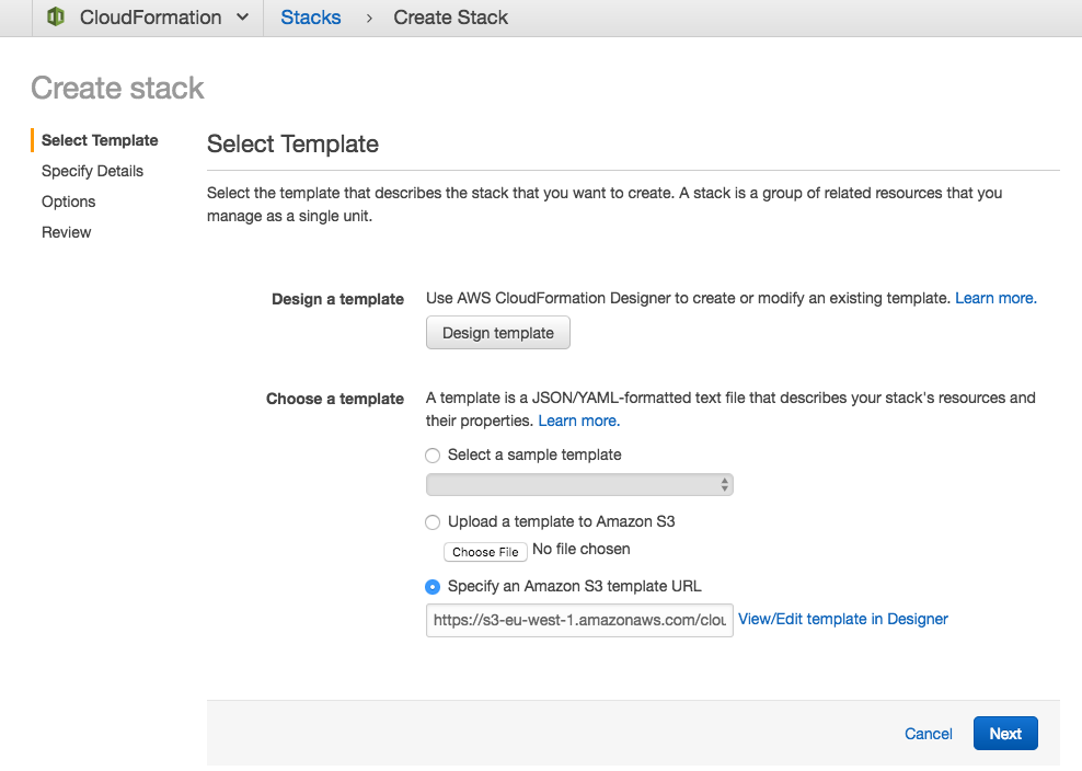
This will redirect you to the AWS CloudFormation console, click “Next” on the first screen.
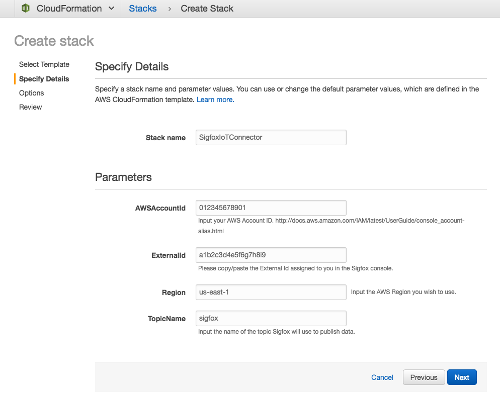
On the following screen, enter the following inputs:
- Stack name: Choose a meaningful name for the connector.
- AWSAccountId: Input your AWS Account Id, you can find it here.
- External Id: Copy/paste the external Id given to you in the Sigfox console.
- Region: Choose the region where AWS IoT will be used.
- Topic Name: Choose the topic name you wish to send data to.
The next screen is optional, if you wish you can customize options (Tags, Permissions, Notifications) otherwise click on “Next” to continue with the default options. You should now be on the review screen, check the “I acknowledge that AWS CloudFormation might create IAM resources” box and click on “Create” to launch the CloudFormation stack.
After a few minutes the provisioning should be completed.

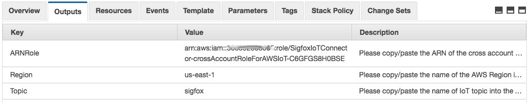
After selecting the AWS CloudFormation stack, click on the “Outputs” tab and copy the value for the “ARNRole” key, the “Region” key and the “Topic” key.
Go Back to the Sigfox console and paste the values you copied from the “Output” section of the AWS CloudFormation stack. Please also fill out the “Json Body” field in the Sigfox console. This JSON represents the payload that will be sent to AWS IoT using the native connector and contains the payload from the connected device as well as some metadata. This is a point for future customization using the Sigfox documentation if you wish to do so.
{
  "device" : "{device}",
  "data" : "{data}",
  "time" : "{time}",
  "snr" : "{snr}",
  "station" : "{station}",
  "avgSnr" : "{avgSnr}",
  "lat" : "{lat}",
  "lng" : "{lng}",
  "rssi" : "{rssi}",
  "seqNumber" : "{seqNumber}"
}
Finally, click “Ok”.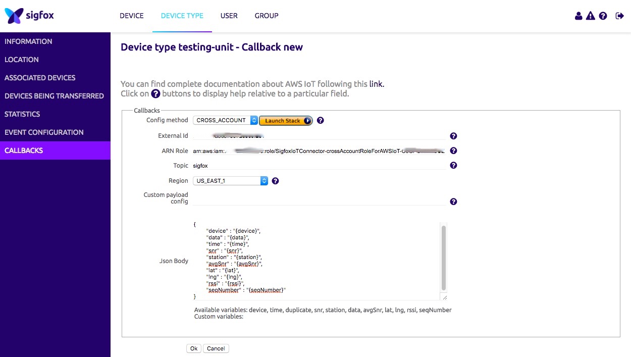
You now have successfully created your callback and can visualize the data sent to it.
Now that the data is being sent to AWS IoT via the native connector, we will create an AWS IoT Rule to store the data into an Amazon DynamoDB table.
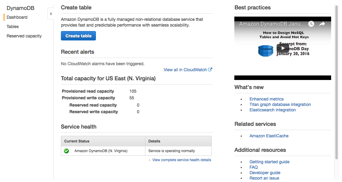
Start by logging into the Amazon DynamoDB table and then click “Create table”.
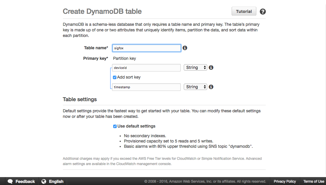
Give the table the name “sigfox” and create a Partition Key “deviceid” as well as a Sort Key “timestamp”. Then create the table.
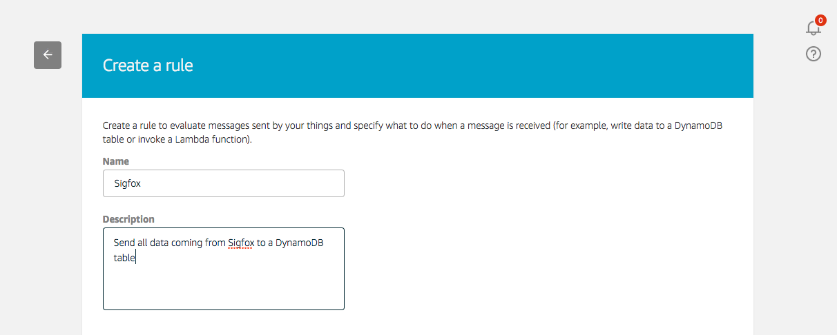
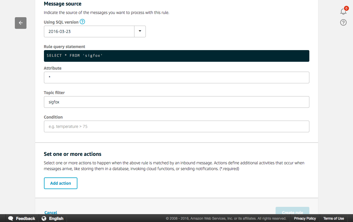
After a couple minutes, the Amazon DynamoDB table is created. Now, go to the AWS IoT console and create a new rule.
Now we will send every message payload coming from Sigfox in its entirety to the DynamoDB table. To do this we are using “*” as the attribute, “sigfox” as the topic filter, and no conditions.
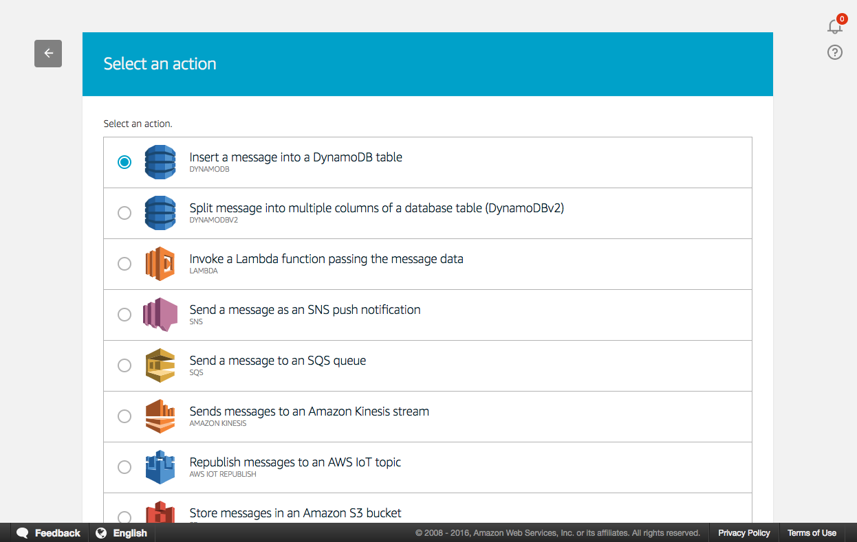
Next add an action, select “Insert a message into a DynamoDB table”.
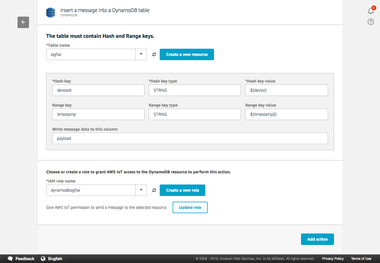
Select the Amazon DynamoDB table we created previously. In the Hash Key value input “${device}” and “${timestamp()}” for the Range Key value. With this configuration, each Device’s ID will represent a Hash Key in the table and data stored under that Hash Key will be ordered using the timestamp generated by the AWS IoT Rules Engine and used as the Sort Key. Finally, create a new role by clicking on the “Create a new role” button. Name it “dynamodbsigfox” and click again on the “Create a new role”, you can now select it in the drop-down list. Thanks to this IAM role, AWS IoT can push data on your behalf to the Amazon DynamoDB table using the “PutItem” permission.
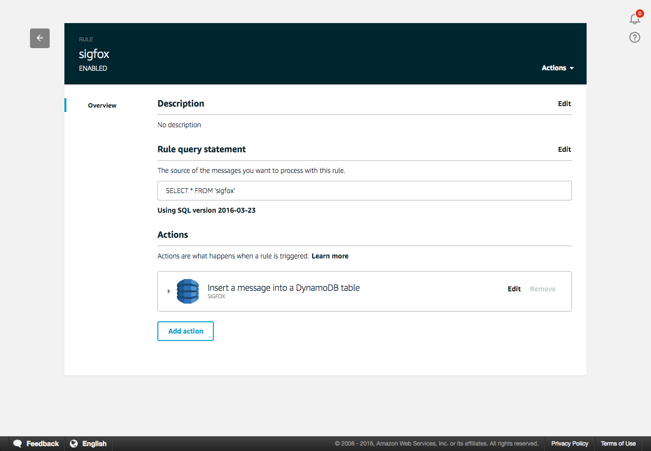
Add the action to the rule and create the rule. You should now be able to visualize the newly created rule in the AWS Console.
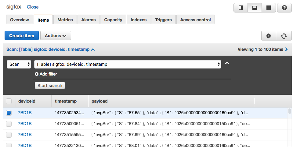
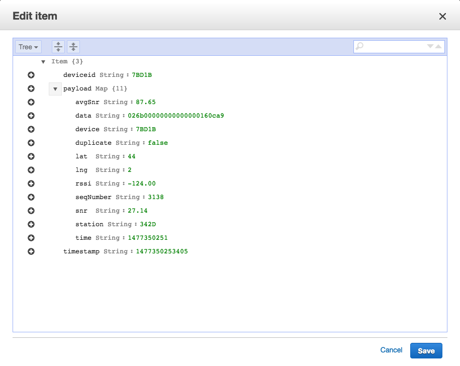
The final step is to go back to the Amazon DynamoDB Console and observe the data sent from Sigfox to AWS IoT thanks to the native connector. That can be achieved by selecting your table and use the “item” tab to observe the items. Once you see the item tab, click on a record to see the payload value.
Using this example’s basic flow, you can now create other AWS IoT rules that route the data to other AWS services. You might want to perform archiving, analytics, machine learning, monitoring, alerting and other functions. If you want to learn more about AWS IoT, here are a few links that should help you:
- AWS IoT website
- AWS IoT State of the Union at RE:Invent 2016
- Youtube playlist of the IoT MiniCon at RE:Invent 2016
Z#BRE testimony – Use case with Sigfox
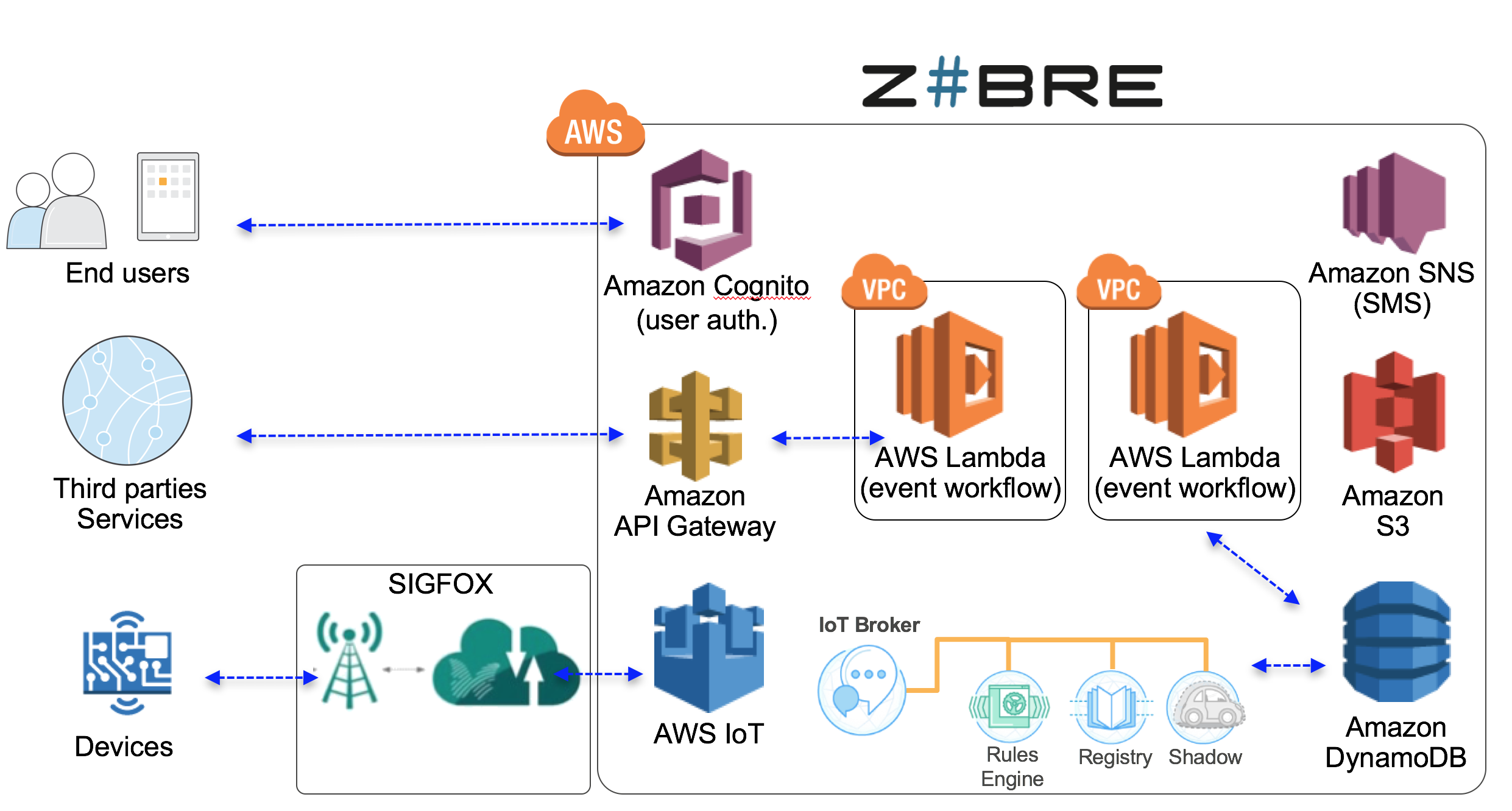
Z#BRE has developed an IoT solution for social care based on AWS IoT and Sigfox: “Z#LINK for Social Care”. The goal is to improve efficiency of social care & create a social link for elderly people. Society is increasingly connected and people are sharing more real-time information with their community. In the context of elderly people, this means they are sharing information with their community, in particular about care they are receiving each day.We have developed a smart object that enables the elderly community (relatives, neighbors, care companies, etc.) to inform their community in real-time whenever a care practitioner delivers care. These real-time insights coming from care data enable public institutions to work better with care companies and to optimize costs while improving care quality.
Thanks to Sigfox connectivity we have created an object that does not require any setup nor Internet connection and can work at least two years with 4 batteries. This object’s use of Sigfox is key when it comes to the simplicity and setup of the overall solution.
Thanks to that simple setup, Sigfox allow faster deployments time of the hardware. With low power consumption and the use of batteries, there is also no need for elderly people to plug or unplug the device, resulting in no risk that they will forget to recharge the device.
Our infrastructure is based on different AWS services as shown in the following diagram:
Our customer, the public council of the Loiret (a department in France), saves 3 million euros per year thanks to the implementation of this solution. More than 10,000 elderly people were equipped over a period of 5 months and more than 70 home care associations were involved in the project. As a result, this initiative was shown to have brought better care quality to elderly people.
Please find more information at https://zbre.io/
Next steps
The release of this native connector is the first step in making it easier for customers to connect Sigfox-enabled objects to the AWS Cloud in order to make use of all the Cloud Computing services available on the AWS platform.We are actively listening to any feedback from customers to continue iterating on this integration in the future and to add more capabilities. Please reach out to sigfox@amazon.com to provide feedback.
As the Sigfox network is growing fast globally, and the AWS IoT platform is adding new features, we are really looking forward to see what new projects customers will be deploying!
IoT for Non-IP Devices
In agriculture, greenhouses are used to create ideal growing conditions to maximize yield. Smart devices allow metrics like light level, temperature, humidity, and wind to be captured not just for historical purposes, but to react quickly to a changing environment. The example used in this blog post involves gathering light readings and activating an infrared-controlled sun shade in the greenhouse based on the current illuminance levels. A lux sensor will be placed directly under the area that we are going to control. Readings will be captured on a minute-by-minute basis. For more complex implementations, you can configure additional sensors and control devices.
Solution Architecture
The IoT implementation has the following features:
- Measures and transmits telemetry once a minute.
- Uses TLS encryption to send telemetry.
- Monitors telemetry and issues alarms when thresholds are exceeded.
- Event notifications are delivered to mobile device through SMS messages.
- IR commands over Ethernet are sent to operate the greenhouse controls.
- Telemetry is logged for reporting purposes.
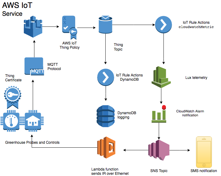
We’re using the MQTT protocol because it is a lightweight yet reliable mechanism for sending telemetry. You can access other AWS services through IoT actions. In this implementation, we used actions to integrate with Amazon CloudWatch and Amazon DynamoDB. CloudWatch logs the telemetry and then raises an alarm if a threshold is breached. Amazon SNS invokes a Lambda function, which sends the IR command in an SNS topic to the remote devices. DynamoDB is used as a long-term, durable store of historic telemetry for reporting purposes.
AWS Services Setup
This implementation uses several AWS services to create an end-to-end application to monitor and control greenhouse devices. In addition to the configuration of each service, we also need to create the roles and policies that will allow these services to work together.IAM
We use IAM roles to provide the appropriate amount of access to the AWS services.Create the CloudWatch role
Step 1. Create the CloudWatch Events role for AWS IoT to use.Copy and paste the following into a file named
aws_iot_role_policy_document.json.This document contains a policy that will ensure that the
aws_iot_cloudwatchMetricrole we create in the next step can assume this role.
{
  "Version": "2012-10-17",
  "Statement": {
    "Effect": "Allow",
    "Principal": {"Service": "iot.amazonaws.com"},
    "Action": "sts:AssumeRole"
  }
}
Step 2. Create an IAM role named aws_iot_cloudwatchMetric.This is the identity used by the AWS IoT action to send telemetry to CloudWatch.
From the command line, run the following command.
aws iam create-role --role-name aws_iot_cloudwatchMetric --
assume-role-policy-document
file://aws_iot_role_policy_document.json
Upon successful execution of this command, an ARN for this role will be returned. Make a note of the ARN for the
aws_iot_cloudwatchMetric.You will need it during the IoT action setup.
Step 3. Create a policy document named
aws_iot_cloudwatchMetric.json.It will allow the
aws_iot_cloudwatchMetricrole to access Amazon CloudWatch.
{
    "Version": "2012-10-17",
    "Statement": {
        "Effect": "Allow",
        "Action": "cloudwatch:PutMetricData",
        "Resource": [
           "*"
        ]
    }
}
Step 4. Attachaws_iot_cloudwatchMetric.jsonto the
aws_iot_cloudwatchMetricrole.
aws iam put-role-policy --role-name aws_iot_cloudwatchMetric --
policy-name aws_iot_cloudwatch_access --policy-document
file://aws_iot_cloudwatchMetric.json
Create the Lambda role
Now we’ll create a second role that will allow AWS Lambda to execute our function.Step 1. Copy and paste the following to a file named aws_lambda_role_policy_document.json.
This document contains a policy that will allow AWS Lambda to assume the role we will create in the next step.
{
   "Version": "2012-10-17",
   "Statement": {
     "Effect": "Allow",
     "Principal": {"Service": "lambda.amazonaws.com"},
     "Action": "sts:AssumeRole"
   }
}
Step 2. Create an IAM role named aws_lambda_execution.This is the identity used by Lambda to execute the function.
aws iam create-role --role-name aws_lambda_execution --assume-
role-policy-document file://aws_lambda_role_policy_document.json
Upon successful execution of this command, an ARN for this role will be returned. Make a note of the ARN for the
aws_lambda_executionrole. You will need it during the Lambda setup.
Step 3. Create the policy document named aws_lambda_execution.json
that will allow the
aws_lambda_executionrole to put events into CloudWatch.
{
  "Version": "2012-10-17",
  "Statement": [
    {
      "Effect": "Allow",
      "Action": [
        "logs:CreateLogGroup",
        "logs:CreateLogStream",
        "logs:PutLogEvents"
      ],
      "Resource": "arn:aws:logs:*:*:*"
    }
  ]
}
Step 4. Attach theaws_lambda_execution.jsonto the
aws_lambda_executionrole.
aws iam put-role-policy --role-name aws_lambda_execution --
policy-name aws_iot_lambda_access --policy-document
file://aws_lambda_execution.json
Create the DynamoDB role
In order to store the telemetry to a persistent data store, we will create a role for AWS IoT to use.Step 1. Create the Lambda execution policy document. Copy and paste the following to a file named aws_dynamodb_role_policy_document.json.
This document contains a policy that will allow DynamoDB to assume this role.
{
   "Version": "2012-10-17",
   "Statement": {
     "Effect": "Allow",
     "Principal": {"Service": "iot.amazonaws.com"},
     "Action": "sts:AssumeRole"
   }
}
Step 2. Create an IAM role named aws_iot_dynamoDB.This is the identity used by AWS IoT to send telemetry to DynamoDB.
aws iam create-role --role-name aws_iot_dynamoDB --assume-role-
policy-document file://aws_iot_dynamoDB_role_policy_document.json
Upon successful execution of this command, an ARN for this role will be returned. Make a note of the ARN for the
aws_iot_dynamoDBrole. You will need it during the DynamoDB setup.
Step 3. Create a policy document named aws_iot_dynamoDB.json
that will allow the
aws_iot_dyanmoDBrole to execute.
{
   "Version": "2012-10-17",
   "Statement": {
     "Effect": "Allow",
     "Action": "dynamodb:PutItem",
     "Resource": "arn:aws:dynamodb:us-east-1:000000000000:table/IoTSensor"
   }
}
Step 4. Attachaws_iot_dynamoDB.jsonto the
aws_iot_dynamoDBrole.
aws iam put-role-policy --role-name aws_iot_dynamoDB --policy-
name aws_iot_dynamoDB_access --policy-document
file://aws_iot_dynamoDB.json
Now that the IAM roles and policies are in place, we can configure AWS IoT and the associated rules.
Set up AWS IoT
Let’s set up AWS IoT as the entry point for device communications. As soon as AWS IoT is communicating with the greenhouse sensors, we will use the AWS IoT rules engine to take further action on the sensor telemetry. The AWS IoT rules engine makes it easy to create highly scalable solutions that integrate with other AWS services, such as DynamoDB, CloudWatch, SNS, Lambda, Amazon Kinesis, Amazon ElasticSearch Service, Amazon S3, and Amazon SQS.Create a thing
From the AWS CLI, follow these steps to create a thing.Step 1. Create a thing that represents the lux meter.
aws iot create-thing --thing-name "greenhouse_lux_probe_1"Step 2. Create the policy.
Start by creating a JSON policy document. It will be linked to the
create policystatement. Copy and paste the following into a document. Be sure to replace 000000000000 with your AWS account number.
   "Version": "2012-10-17",
   "Statement": [
{
       "Effect": "Allow",
       "Action": [
         "iot:Connect"
       ],
       "Resource": [
         "arn:aws:iot:us-east-1:000000000000:client/${iot:ClientId}"
       ]
     },
     {
        "Effect": "Allow",
        "Action": [
          "iot:Publish"
        ],
        "Resource": [
          "arn:aws:iot:us-east-1:000000000000:topic/Greenhouse/${iot:ClientId}"
      ]
    }
  ]
}
Now, run the following command to create the policy. Be sure to include the full path to the policy document.aws iot create-policy --policy-name "greenhouse_lux_policy" -- policy-document file://iot_greenhouse_lux_probe_policy.jsonStep 3. Create a certificate.
Creating a certificate pair is a simple process when you use the AWS IoT CLI. Use the following command to create the certificate, mark it as active, and then save the keys to the local file system. These keys will be required for authentication between the thing and AWS IoT.
aws iot create-keys-and-certificate --set-as-active --
certificate-pem-outfile IoTCert.pem.crt --public-key-outfile
publicKey.pem.key --private-key-outfile privateKey.pem.key
Step 4. Attach the thing and policy to the certificate.
Using the following as an example, replace 000000000000 with your AWS account number and 22222222222222222222222222222222222222222222 with your certificate ARN. This will attach the thing to the certificate.
aws iot attach-thing-principal –thing-name
greenhouse_lux_probe_1 –principal arn:aws:iot:us-east-
1:000000000000:cert/22222222222222222222222222222222222222222222
Now, attach the policy to the certificate.
aws iot attach-principal-policy --policy-name
greenhouse_lux_policy --principal arn:aws:iot:us-east-
1:000000000000:cert/22222222222222222222222222222222222222222222
Now that you have created a thing, policy, and certificate, you might also want to test connectivity to AWS IoT using a program like aws-iot-elf, which is available from the AWS Labs Github repo. After you have confirmed connectivity, you can build out the remainder of the application pipeline.
Configure the AWS IoT rules engine
Creating rules is an extremely powerful and straightforward way to build a responsive, extensible architecture. In this example, we will record and respond to telemetry as fast as we can record and report it. Letís imagine we need to ensure that the crop is not exposed to light intensity greater than 35,000 lux. First, we will integrate AWS IoT with CloudWatch, so it can be used to decide what to do based on the received telemetry. Two rules are required to support this case: one rule called TooBright and a second rule called NotTooBright.Step 1. Create a JSON file named create-TooBright-rule.json
with the following content to serve as the rule policy. Be sure to use your AWS account number and the ARN for the
aws_iot_cloudwatchMetricrole.
{
   "sql": "SELECT * FROM '/topic/Greenhouse/LuxSensors' WHERE
lux > 35000",
   "description": "Sends telemetry above 35,000 lux to
CloudWatch to generate an alert",
   "actions": [
   {
       "cloudwatchMetric": {
           "metricUnit" : "Count",
           "roleArn":
"arn:aws:iam::000000000000:role/aws_iot_cloudwatchMetric",
           "metricValue" : "1",
           "metricNamespace" : "Greenhouse Lux Sensors",
           "metricName" : "ShadePosition"
               }
           }
       ],
    "awsIotSqlVersion": "2016-03-23",
    "ruleDisabled": false
}
Step 2. From the command line, run this command to create the rule.aws iot create-topic-rule --rule-name TooBright --topic-rule- payload file://create-TooBright-rule.jsonStep 3. Create a JSON file named create-NotTooBright-rule.json
with the following content to serve as the rule policy. Be sure to use the AWS account number and ARN for the
aws_iot_cloudwatchMetricrole that you created earlier. Change the WHERE clause to < 35000 and the metricValue to 0.
{
   "sql": "SELECT * FROM '/topic/Greenhouse/LuxSensors' WHERE
lux < 35000",
   "description": "Sends telemetry above 35,000 lux to
CloudWatch to generate an alert",
   "actions": [
   {
       "cloudwatchMetric": {
           "metricUnit" : "Count",
           "roleArn":
"arn:aws:iam::000000000000:role/aws_iot_cloudwatchMetric",
           "metricValue" : "0",
           "metricNamespace" : "Greenhouse Lux Sensors",
           "metricName" : "ShadePosition"
               }
           }
       ],
   "awsIotSqlVersion": "2016-03-23",
   "ruleDisabled": false
}
Step 4. From the command line, run this command to create the rule.aws iot create-topic-rule --rule-name NotTooBright --topic-rule- payload file://create-NotTooBright-rule.json
Set up SNS
We will configure SNS to invoke the Lambda function and deliver an SMS message to a mobile phone. The SMS notification functionality is useful for letting the greenhouse operations team know the system is actively monitoring and controlling the greenhouse devices. Setting up SNS for this purpose is a simple process.Step 1. Create the SNS topic.
aws sns create-topic --name SunshadesThe SNS service returns the ARN of the topic.
{
    "TopicArn": "arn:aws:sns:us-east-1:000000000000:Sunshades"
}
Step 2. Using the topic ARN and a phone number where the SMS message should be sent, create a subscription.aws sns subscribe --topic-arn arn:aws:sns:us-east-
1:000000000000:Sunshades --protocol SMS --notification-endpoint "1 555 555 5555"
The SNS service confirms the subscription ID.{
"SubscriptionArn": "arn:aws:sns:us-east-
1:000000000000:Sunshades:0f1412d1-767f-4ef9-9304-7e5a513a2ac1"
}
Set up Lambda
We are going to use a Lambda function written in Python to make a socket connection to the remote Ethernet-to-IR device that controls the sun shade.Step 1. Sign in to the AWS Management Console, and then open the AWS Lambda console. Choose the Create a Lambda function button.
Step 2. On the blueprint page, choose Configure triggers.
Step 3. On the Configure triggers page, choose SNS. From the SNS topic drop-down list, choose the Sunshades topic.
Step 4. Select the Enable trigger check box to allow the SNS topic to invoke the Lambda function, and then choose Next.
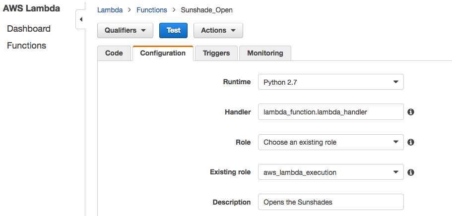
Step 6. On the Configure function page, type a name for your function (for example, Sunshade_Open).
Step 7. From the Runtime drop-down box, choose Python 2.7.
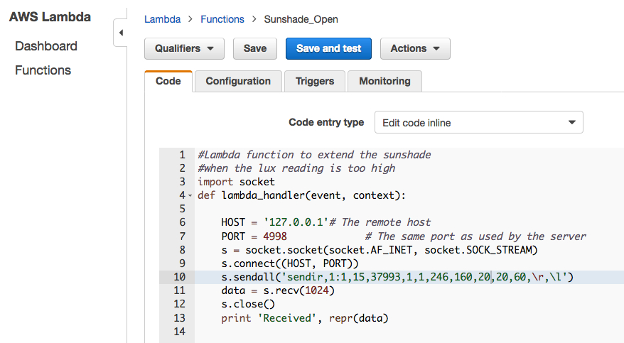
Step 8. Copy and paste the following Python code to create the Lambda functions that will open the sun shades. Be sure to use the IP address and port of the remote Ethernet-to-IR communication device. Include the IR code for your device as provided by the manufacturer.
You can get the IR code through the learning function of the IR repeater. This process typically requires sending an IR signal to the IR repeater so that it can capture and save the code as binary. The binary values for the IR command are then sent as part of the IP packet destined for the IR repeater.
Lambda function to open the sun shade
#Lambda function to extend the sunshade
#when the lux reading is too high
import socket
def lambda_handler(event, context):
HOST = 'xxx.xxx.xxx.xxx'# The remote host
PORT = 4998             # The same port as used by the server
s = socket.socket(socket.AF_INET, socket.SOCK_STREAM)
s.connect((HOST, PORT))
s.sendall('sendir,1:1,15,37993,1,1,246,160,20,20,60,\r,\l')
data = s.recv(1024)
s.close()
print 'Received', repr(data)
In Role, choose an existing role. In Existing role, choose theaws_lambda_executionrole you created earlier, and then choose Next.
On the following page, review the configuration, and then choose Create function.
Choose the blue Test button and leave the default Hello World template as it is. Choose Save and Test to see if the function ran successfully. The Lambda function should have issued the remote IR command, so check to see if the sun shade device responded to the Lambda invocation. If the execution result is marked failed, review the logs on the test page to determine the root cause. If the Lambda function was successful but the sun shade did not move, double-check that you used the appropriate IR codes.
Now create the second Lambda function. ‘Sunshade_Close’ will be similar to ìSunshade_Open,’ except it will contain the IR code for closing the shade.
Set up CloudWatch
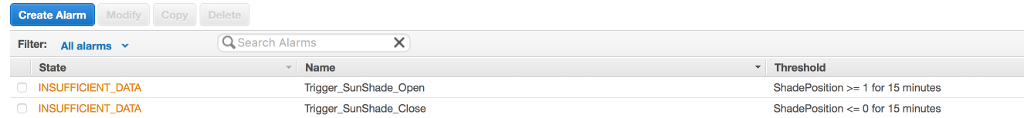
We send a metric value of either 0 or 1 from the AWS IoT action to CloudWatch to indicate whether the sun shade should be opened or closed. In this example, 0 indicates that the lux level is below 35,000 and the shades should be open. 1 indicates a higher lux level that requires the sun shades to be closed. Weíll have a problem if the power to the devices is cycled too frequently. Not only is this an inefficient way to control devices, it can also damage the equipment. For this reason, we will use CloudWatch alarms to set a threshold of 15 minutes to prevent devices from cycling between open and closed states too frequently. Each alarm will have triggers that respond to the value you put in the metric name type when you created the AWS IoT action.The first alarm is called Trigger_SunShade_Open. This alarm will trigger when the variable ShadePosition value is greater or equal to 1 for 15 consecutive minutes. We will treat the ShadePosition value as a binary value where 1 indicates the lux is above the threshold and the sun shade should be opened. A value of 0 indicates that the sun shade should be closed. We define the period as a one-minute interval, which means the sun shade will change states no sooner than every 15 minutes. A second alarm called Trigger_SunShade_Close is created in the same way, except that the ShadePosition must be less than 1 for 15 minutes. Both alarms are configured with an action to send a notification to the appropriate SNS topic.
aws cloudwatch put-metric-alarm --alarm-name "Trigger_SunShade_Open"
--namespace "Greenhouse Lux Sensors" --metric-name "ShadePosition"
--statistic Sum --evaluation-periods "15"
--comparison-operator "GreaterThanOrEqualToThreshold"
--alarm-actions arn:aws:sns:us-east-1:000000000000:Sunshades
--period "60" --threshold "1.0" --actions-enabled
Next, create the
Trigger_Sunshade_Closealarm in a similar manner to
Trigger_SunShade_Open.This alarm will trigger when the ShadePosition value is 1.
aws cloudwatch put-metric-alarm --alarm-name "Trigger_SunShade_Close"
--namespace "Greenhouse Lux Sensors" --metric-name "ShadePosition"
--statistic Sum --evaluation-periods "15"
--comparison-operator "LessThanOrEqualToThreshold"
--alarm-actions arn:aws:sns:us-east-1:000000000000:Sunshades
--period "60" --threshold "0" --actions-enabled
Sign in to the AWS Management Console, open the CloudWatch console, and then look at the alarms.
Confirm the two alarms were created. Because of the 15-minute evaluation period, you need to wait 15 minutes to verify the alarms are working.
Depending on the reported value of the ShadePosition variable, the state displayed for one alarm should be OK and the other should be ALARM.
After 15 minutes, we see the
Trigger_Sunshade_Closealarm is in the OK state, which means the alarm has not been raised and therefore the sun shade should be not closed.
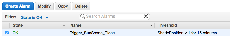
Conversely,
Trigger_Sunshade_Openis in an ALARM state, which indicates the sun shade should be open.
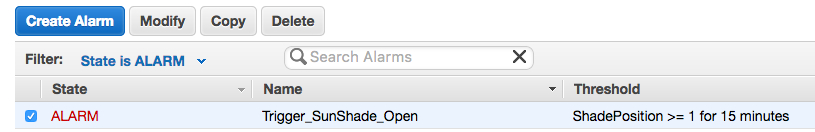
This alarm state should also have generated an SMS message to the mobile device that was configured in the SNS topic.
Set up DynamoDB
DynamoDB is the repository for the historical lux readings because of its ease of management, low operating costs, and reliability. We’ll use an AWS IoT action to stream telemetry directly to DynamoDB. To get started, create a new DynamoDB table.aws dynamodb create-table --table-name Greenhouse_Lux_Sensor -- attribute-definitions AttributeName=item,AttributeType=S AttributeName=timestamp,AttributeType=S --key-schema AttributeName=item,KeyType=HASH AttributeName=timestamp,KeyType=RANGE --provisioned-throughput ReadCapacityUnits=1,WriteCapacityUnits=1DynamoDB will return a description of the table to confirm it was created.
AWS IoT DynamoDB Action
Step 1. Create a JSON file named create-dynamoDB-rule.jsonwith the following content to serve as the rule policy. Use your AWS account number and the ARN for the
aws_iot_dynamoDBrole you created earlier.
{
   "sql": "SELECT * FROM '/topic/Greenhouse/LuxSensors/#'",
   "ruleDisabled": false,
   "awsIotSqlVersion": "2016-03-23",
   "actions": [{
       "dynamoDB": {
           "tableName": "Greenhouse_Lux_Sensor",
           "roleArn":
"arn:aws:iam::000000000000:role/aws_iot_dynamoDB",
           "hashKeyField": "item",
           "hashKeyValue": "${Thing}",
           "rangeKeyField": "timestamp",
           "rangeKeyValue": "${timestamp()}"
       }
   }]
}
Step 2. From the command line, run this command to create the rule.aws iot create-topic-rule --rule-name Lux_telemetry_to_DynamoDB - -topic-rule-payload file://crate-dynamoDB-rule.jsonExecute this command to verify that telemetry is successfully being sent to DynamoDB.
aws dynamodb scan --table-name Greenhouse_Lux_Sensor --return-
consumed-capacity TOTAL
This command will scan the DynamoDB table and return any data that was written to it. In addition, it will return a ScannedCount with the number of objects in the table. If the ScannedCount is 0, make sure that telemetry is being sent to and received by AWS IoT.
Summary
You now have a fully functional AWS IoT implementation that provides intelligent control of not-so-smart devices. You have also created a completely serverless solution that can serve a single device or billions of them, all without changing the underlying architecture. Lastly, charges for the services used in this implementation are based on consumption, which yields a very low TCO.There are infinite uses for AWS IoT when you combine its cloud logic with the devices and sensors on the market. This post has shown the power of this AWS service can be extended to non-IP devices, which can now be managed and controlled as if they were designed for IoT applications.
Access Cross Account Resources Using the AWS IoT Rules Engine
This blog post explains how to set up rules for cross-account data ingestion, from an MQTT topic in one account, to a destination in another account. We will focus on the cross-account access from an MQTT topic (the source) to Lambda and SQS (the destinations).
The blog has been written with the assumption that you are familiar with AWS IoT and the Rules Engine, and have a fair understanding of AWS IAM concepts like users, role and resource-based permission.
We are going to use the AWS CLI to setup cross-account rules. If you don’t have AWS CLI installed, you can follow these steps. If you have the AWS CLI installed, make sure you are using the most recent version.
Why do you need cross-account access via rules engine?
Rules with cross-account access allow you to ingest data published on an MQTT topic in one account to a destination (S3, SQS etc.) in another account. For example, Weather Corp collects weather data using its network of sensors and then publishes that data on MQTT topics in its AWS account. Now, if Weather Corp wishes to publish this data to an Amazon SQS queue of its partner, Forecast Corp’s, AWS account, they can do so by enabling cross-account access via the AWS IoT Rules Engine.How can you configure a cross-account rule?
Cross-account rules can be configured using the resource-based permissions on the destination resource.Thus, for Weather Corp to create a rule in their account to ingest weather data into an Amazon SQS queue in Forecast Corp’s AWS account, the cross account access can be set up by means of the two step method stated below:
- Forecast Corp creates a resource policy on their Amazon SQS queue, allowing Weather Corp’s AWS account to sqs:SendMessage action.
- Weather Corp configures a rule with the Forecast Corp queue URL as its destination.
Amazon Simple Queue Service (SQS)
Amazon Simple Notification Service (SNS)
Amazon Simple Storage Service (S3)
AWS Lambda
Amazon Simple Notification Service (SNS)
Amazon Simple Storage Service (S3)
AWS Lambda
Configure a cross-account rule
In this section, configuration of a cross account rule to access an AWS Lambda function and Amazon SQS queue in a different account has been explained. We used the AWS CLI for this configuration.Steps to configure a cross-account rule for AWS Lambda is different when compared to other AWS services that support resource policy.
For Lambda:
The AWS IoT Rules Engine, mandatorily requires resource-based policy to access Lambda functions; so a cross-account Lambda function invocation is configured just like any other IoT-Lambda rule. The process of enabling cross-account access for Lambda can be understood from the following example:Assume that Weather Corp, using AWS account# 123456789012, wishes to trigger a Lambda function (LambdaForWeatherCorp) in Forecast Corp’s account (AWS account# 987654321012) via the Rules Engine. Further, Weather Corp wishes to trigger this rule when a message arrives on Weather/Corp/Temperature MQTT topic.
To do this, Weather Corp would need to create a rule (WeatherCorpRule) which will be attached to Weather/Corp/Temperature topic. To create this rule, Weather Corp would need to call the CreateTopicRule API. Here is an example of this API call via AWS CLI:
aws iot create-topic-rule --rule-name WeatherCorpRule --topic-rule-payload file://./lambdaRuleContents of the lambdaRule file:
{
       "sql": "SELECT * FROM 'Weather/Corp/Temperature'",
       "ruleDisabled": false,
       "actions": [{
           "lambda": {
               "functionArn": "arn:aws:lambda:us-east-1:987654321012:function:LambdaForWeatherCorp"   //Cross account lambda
            }
       }]
}
Forecast Corp will also have to give the AWS IoT Rules
Engine permission to trigger LambdaForWeatherCorp Lambda function. Also,
it is very important for Forecast Corp to make sure that only the AWS
IoT Rules Engine is able to trigger the Lambda function and that it is
done so only on behalf of Weather Corp’s WeatherCorpRule (created above)
rule.To do this, Forecast Corp would need to use Lambda’s AddPermission API. Here is an example of this API call via AWS CLI:
aws lambda add-permission --function-name LambdaForWeatherCorp --region us-east-1 --principal iot.amazonaws.com --source-arn arn:aws:iot:us-east-1:123456789012:rule/WeatherCorpRule --source-account 123456789012 --statement-id "unique_id" --action "lambda:InvokeFunction"Options:
–principal: This field gives permission to AWS IoT (represented by iot.amazonaws.com) to call the Lambda function.
–source-arn: This field makes sure that only arn:aws:iot:us-east-1:123456789012:rule/WeatherCorpRule rule in AWS IoT triggers this Lambda (no other rule in the same or different account can trigger this Lambda).
–source-account: This field makes sure that AWS IoT triggers this Lambda function only on behalf of 123456789012 account.
Note: To run the above command, IAM user/role should have permission to lambda:AddPermission action.
For Other Services
As of today, the Rules Engine does not use resource policy to access non-Lambda AWS resources (Amazon SQS, Amazon S3, Amazon SNS ). Instead, it uses IAM role to access these resources in an account. Additionally, AWS IoT rules can only be configured with roles from the same account. This implies, that a rule cannot be created in one account that uses a role from another account.While, a role from another account cannot be used in a rule, a role can be set up in an account to access resources in another account. Also, for a cross-account role to work, you need a resource policy on the resource that has to be accessed across the account.
The process of rule creation with access to cross-account resources can be understood from the below example:
Let’s assume that Weather Corp, using AWS account# 123456789012, wishes to send some data to Amazon SQS (SqsForWeatherCorp) in Forecast Corp’s account (AWS account# 987654321012) via rules engine. If Weather Corp wishes to trigger this rule when a message arrives on Weather/Corp/Temperature MQTT topic.
To do this, Weather Corp would need to do the following things:
Step 1: Create an IAM policy (PolicyWeatherCorp) that defines cross-account access to SqsForWeatherCorp SQS queue. To do this, Weather Corp would need to call IAM’s CreatePolicy API. Here is an example of this API call via AWS CLI:
aws iam create-policy --policy-name PolicyWeatherCorp --policy-document file://./crossAccountSQSPolicyWhere the contents of crossAccountSQSPolicy file are below:
{
   "Version": "2012-10-17",
   "Statement": [
       {
           "Sid": “unique”,
           "Effect": "Allow",
           "Action": [
               "sqs:SendMessage"
           ],
           "Resource": [
               "arn:aws:sqs:us-east-1:987654321012:SqsForWeatherCorp" //Cross account SQS queue
           ]
       }
   ]
}
Step 2: Create a role (RoleWeatherCorp) that defines
iot.amazonaws.com as a trusted entity. To do this Weather Corp would
need to call IAM’s CreateRole API. Here is an example of this API call
via AWS CLI:aws iam create-role --role-name RoleWeatherCorp --assume-role-policy-document file://./roleTrustPolicyWhere the contents of roleTrustPolicy file are below:
{
 "Version": "2012-10-17",
 "Statement": [
   {
     "Sid": "",
     "Effect": "Allow",
     "Principal": {
       "Service": "iot.amazonaws.com"
     },
     "Action": "sts:AssumeRole"
   }
 ]
}
Step 3: Attach policy to role. To do this, Weather Corp
would need to call AttachRolePolicy API. Here is an example of this API
call via AWS CLI:aws iam attach-role-policy --role-name RoleWeatherCorp --policy-arn arn:aws:iam::123456789012:policy/PolicyWeatherCorpStep 4: Create a rule (WeatherCorpRule) that is attached to Weather/Corp/Temperature topic. To create this rule, Weather Corp would need to call CreateRule API. Here is an example of this API call via AWS CLI:
aws iot create-topic-rule --rule-name WeatherCorpRule --topic-rule-payload file://./sqsRuleWhere the contents of sqsRule file are below:
{
       "sql": "SELECT * FROM 'Weather/Corp/Temperature'",
       "ruleDisabled": false,
       "actions": [{
           "sqs": {
               "queueUrl": "https://sqs.us-east-1.amazonaws.com/987654321012/SqsForWeatherCorp",
               "roleArn": "arn:aws:iam::123456789012:role/RoleWeatherCorp”,
               "useBase64": false
           }
       }]
}
Note: To run the above command, IAM user/role should have
permission to iot:CreateTopicRule with rule arn as resource. Also, it
needs to have permission to iam:PassRole action with resource as role
arn.Further, Forecast Corp would need to give permission on SqsForWeatherCorp to Weather Corp’s account, using resource policy. This can be done using SQS’s add-permission API. Here is an example of this API call via AWS CLI:
aws sqs add-permission --queue-url https://sqs.us-east-1.amazonaws.com/987654321012/SqsForWeatherCorp --label SendMessagesToMyQueue --aws-account-ids 123456789012 --actions SendMessageIt is important to note, that by adding this resource policy, Forecast Corp not only allows AWS IoT rules engine to send messages to SqsForWeatherCorp, but also permits all users/roles in Weather Corp’s account (which have the policy to allow sqs:SendMessage to SqsForWeatherCorp) to send messages to SqsForWeatherCorp.
Once the above setup is done, all messages sent to Weather/Corp/Temperature (which is in WeatherCorp’s account) will be sent to SqsForWeatherCorp (which is in Forecast Corp’s account) using the rules engine.
Conclusion
In this blog, the process of creating AWS IoT rules with cross account destination has been explained. With the help of simple case scenarios, the process of creating rules for Lambda and SQS destinations, using AWS CLI, has been detailed in a step by step manner.We hope you found this walkthrough useful. Feel free to leave your feedback in the comments.
Identify APN Partners to Help You Build Innovative IoT Solutions on AWS
We are currently witnessing a major shift in how customers view their business. Customers across industries, including Financial Services, Manufacturing, Energy, Transportation, Industrial and Banking, are on a business transformation journey and are seeking guidance to help transform from product-centric to service-orientated companies, taking advantage of actionable insights they can drive through IoT. Early adopters have already deployed a wide range of cloud-based IoT solutions, and many are seeking to optimize existing solutions. Some companies are just getting started. Regardless of where your company is in your IoT journey, working with industry-leading AWS Partner Network (APN) Partners who offer value-added services and solutions on AWS can help you accelerate your success.
Today, we launched the AWS IoT Competency to help you easily connect to APN Partners with proven expertise and customer success to help meet your specific business needs.
What’s the value of the AWS IoT Competency for your firm?
The IoT value chain is complex, and has many “actors.” Successful IoT implementations require services and technologies not traditionally part of the Enterprise DNA. As you seek to find best-in-breed partners for your specific needs, whether they be identifying edge or gateway devices or software, a platform to acquire, analyze, and act on IoT data, connectivity for edge and gateway devices, or consulting services to help you architect and deploy your solution, we want to make sure we help you easily connect with Consulting and Technology Partners who can help.APN Partners who have achieved the AWS IoT Competency have been vetted by AWS solutions architects, and have passed a high bar of requirements such as providing evidence of deep technical and consulting expertise helping enterprises adopt, develop, and deploy complex IoT projects and solutions. IoT Competency Partners provide proven technology and/or implementation capabilities for a variety of use cases including (though not limited to) intelligent factories, smart cities, energy, automotive, transportation, and healthcare. Lastly, public customer references and proven customer success are a core requirement for any APN Partner to achieve the AWS IoT Competency.
Use Cases and Launch Partners
Congratulations to our launch IoT Technology Competency Partners in the following categories:Edge: Partners who provide hardware and software ingredients used to build IoT devices, or finished products used in IoT solutions or applications. Examples include: sensors, microprocessors and microcontrollers, operating systems, secure communication modules, evaluation and demo kits.
- Intel
- Microchip Technology
- MachineShop
- Bsquare Corporation
- C3 IoT
- Splunk
- PTC
- Thinglogix
- Amdocs, Inc.
- Asavie
- Eseye
- SORACOM
- Accenture
- Aricent
- Cloud Technology Partners
- Mobiquity, Inc.
- Luxoft
- Solstice
- Sturdy
- Trek10
Learn More
Hear from two of our launch AWS IoT Competency Partners, MachineShop and C3 IoT, as they discuss why they work with AWS, and the value of the AWS IoT Competency for customers:C3 IoT:
MachineShop:
Want to learn more about the different IoT Partner Solutions? Click here.
Improved AWS IoT Management Console
In the new console, you will see:
- New visual design for improved usability and navigation
- Improved navigation to things, types, certificates, policies, and rules, making them easier to find
- A new dashboard with account-level metrics
- Streamlined MQTT web client to troubleshoot your IoT solutions
- A new wizard to connect devices in fewer steps
- A real-time feed of things’ lifecycle events and shadow activity
Your feedback is important to us as we continue to improve the AWS IoT console experience. To send feedback, please use the Feedback button in the footer of the console.
Fig 1 – New dashboard with account-level metrics.

Fig 2 – Things, types, certificates, policies, and rules all have their own areas.

Fig 3 – Drill in to resource details and take action.

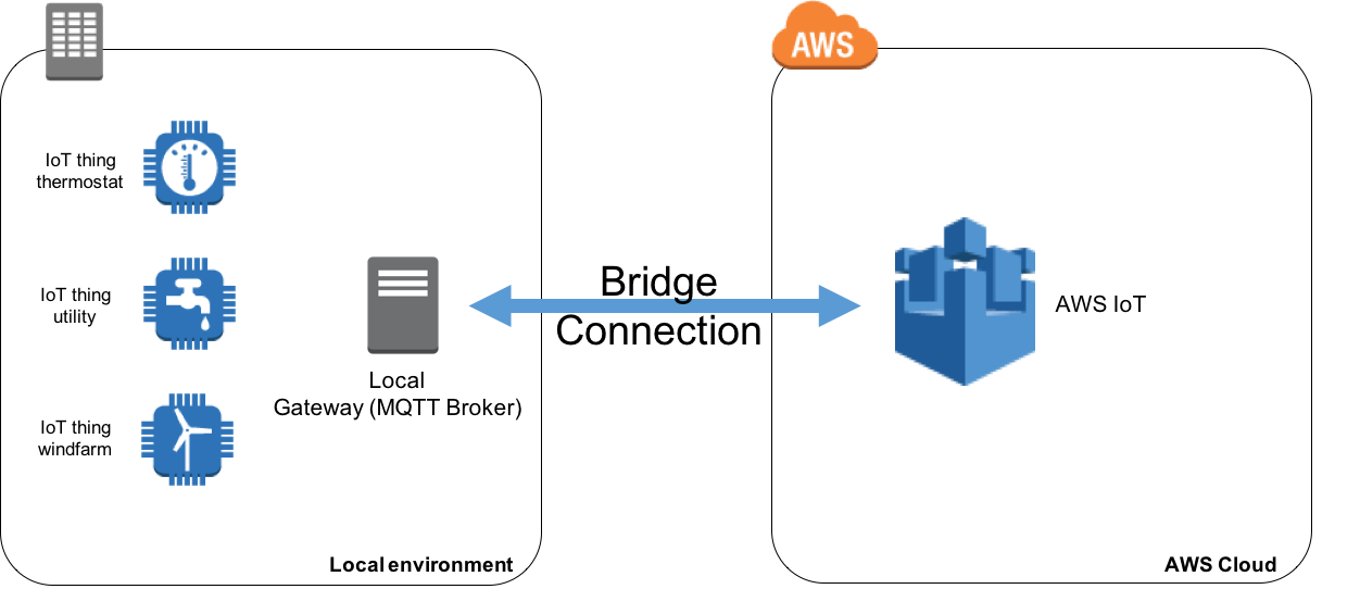
How to Bridge Mosquitto MQTT Broker to AWS IoT
One feature of local MQTT broker is called ‘Bridge’ and will enable you to connect your local MQTT broker to AWS IoT so they can exchange MQTT messages. This will enable your objects to communicate in a bi-directional fashion with AWS IoT and benefit from the power of the AWS Cloud.
In this article we are going to explain use cases where this feature can be very useful and show you how to implement it.
Why Bridge your MQTT Broker to AWS IoT
Security is paramount in IoT and the AWS IoT broker has a high level of security built-in to authenticate and authorize devices base on standards like TLS 1.2 with client certificates.If you have legacy IoT deployments, you might already have objects connected to an MQTT broker using other authentication mechanism like username and passwords. Your MQTT broker can be very close to where your sensors are deployed (local MQTT broker) or in a remote location like the Cloud.
If you plan to upgrade your current security standards to match those of AWS IoT but want to benefit from the scalability and Rule Engine of AWS IoT today, you can bridge your legacy MQTT broker to AWS IoT. This represents an easy transient solution that you can deploy quickly without having to wait for your current system’s upgrade. Scaling beyond a single broker is not in the scope of this post, we will focus on the bridging feature of Mosquitto MQTT Broker.
Open source MQTT broker like Mosquitto can be installed on many operating systems like Linux for example. For those wishing to deploy a local gateway quickly without developing extra code to send data to AWS IoT, installing Mosquitto on a local device can represent an attractive solution as well as you will benefit locally from Mosquitto boker’s features (persist messages locally, log activity locally, …).
How to Install Mosquitto MQTT Broker
The first step will be to install Mosquitto broker on your device/virtual machine, you can go to Mosquitto download page for instructions.Typically, you should install this on your local gateway. Mosquitto supports a wide range of platforms including many distributions of Linux. Therefore, you can run your local gateway on low powered devices as well as on a full-fledged server/virtual machine.
In our case we will install Mosquitto on an EC2 Amazon Linux instance which would be equivalent to having a local gateway running a Linux distribution.
If you are not planning on using an Amazon EC2 Instance you can skip to the section “How to configure the bridge to AWS IoT”
Launching and Configuring the EC2 Instance
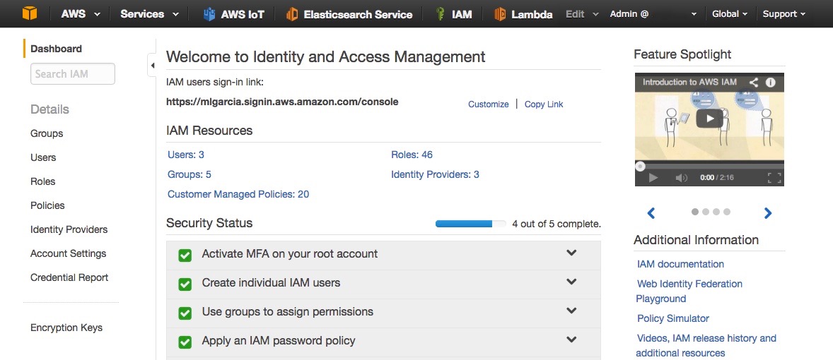
Before launching an EC2 Amazon Linux instance to host the Mosquitto broker, we are going to create an IAM Role so we’ll be able to use the CLI on the instance to create keys and certificate in AWS IoT for the bridge.- Go to the AWS Web Console and access the IAM service (Fig. 1)
- Click on Roles
- Click on Create New Role (Fig. 2)
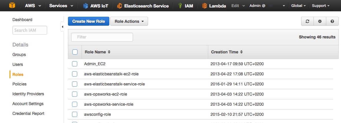
- Name the role AWSIoTConfigAccess (Fig. 3)
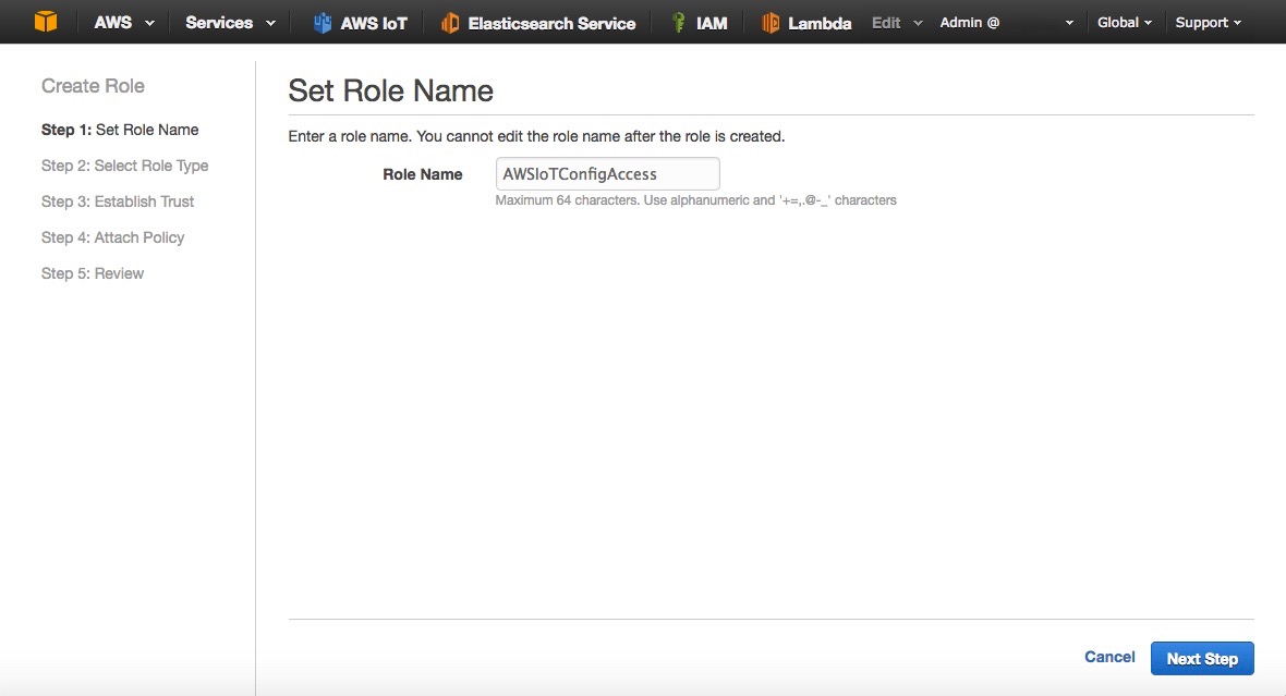
- Click Next Step
- Select Amazon EC2 (Fig. 4)

- Filter with the value AWSIoTConfigAccess (Fig. 5)
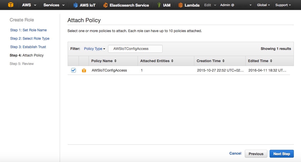
- Select the policy AWSIoTConfigAccess and click on Next Step
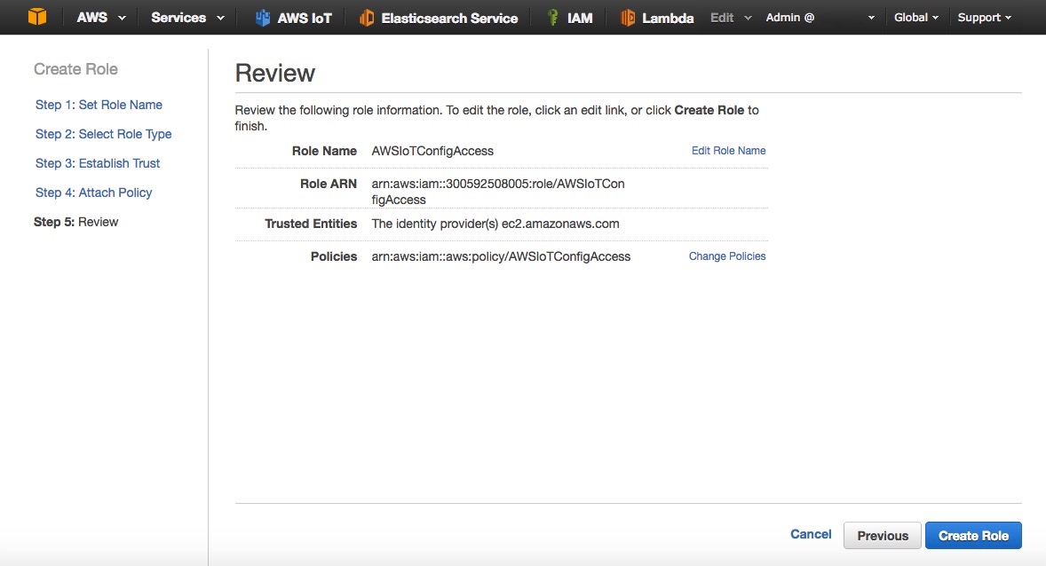
- Review the Role and click on Create Role (Fig. 6)
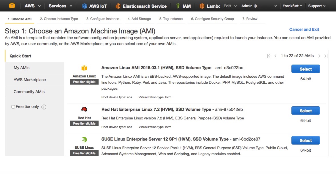
- Now that the Role has been created you can go to Amazon EC2. Choose a region, preferably where AWS IoT is available, in this article I am using Frankfurt.
- Click on Launch Instance.
- Select Amazon Linux AMI 2016.03.1 (Fig. 7)
- Select the t2.micro instance type (Fig. 8)
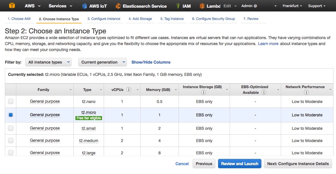
- Click on Next: Configure Instance Details
- In the IAM Role, select AWSIoTConfigAccess (Fig. 9)
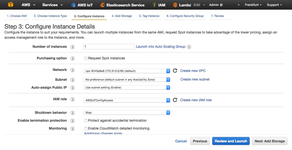
- Leave default parameters as shown in the picture and click on Next: Add Storage
- Leave everything as is and click on Next: Tag Instance
- Give a name to your instance ‘MosquittoBroker’
- Click on Next: Configure Security Groups
- Create a new security group (Fig. 10)
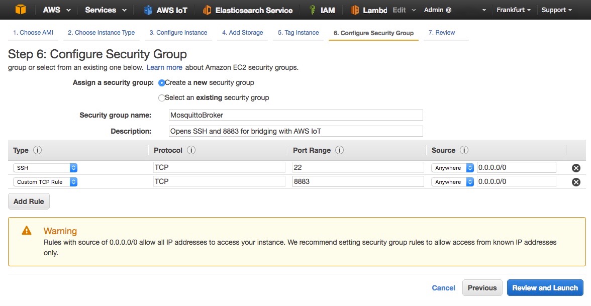
- Review and launch the EC2 instance
- Follow instructions to connect to the EC2 instance once it is running.
- Once logged in type the following commands:
#Update the list of repositories with one containing Mosquitto
sudo wget http://download.opensuse.org/repositories/home:/oojah:/mqtt/CentOS_CentOS-7/home:oojah:mqtt.repo -O /etc/yum.repos.d/mqtt.repo
#Install Mosquitto broker and Mosquitto command line tools
sudo yum install mosquitto mosquitto-clients
How to Configure the Bridge to AWS IoT
Now that we have installed Mosquitto onto our EC2 instance (or local gateway), we will need to configure the bridge so that the Mosquitto broker can create a connection to AWS IoT. We will first use the AWS CLI to create the necessary resources on AWS IoT side.Enter the following commands in your terminal:
#Configure the CLI with your region, leave access/private keys blank
aws configure

#Create an IAM policy for the bridge
aws iot create-policy --policy-name bridge --policy-document '{"Version": "2012-10-17","Statement": [{"Effect": "Allow","Action": "iot:*","Resource": "*"}]}'

#Place yourself in Mosquitto directory
#And create certificates and keys, note the certificate ARN
cd /etc/mosquitto/certs/
sudo aws iot create-keys-and-certificate --set-as-active --certificate-pem-outfile cert.crt --private-key-outfile private.key --public-key-outfile public.key –region eu-central-1

#List the certificate and copy the ARN in the form of
# arn:aws:iot:eu-central-1:0123456789:cert/xyzxyz
aws iot list-certificates

#Attach the policy to your certificate
aws iot attach-principal-policy --policy-name bridge --principal <ARN_OF_CERTIFICATE>

#Add read permissions to private key and client cert
sudo chmod 644 private.key
sudo chmod 644 cert.crt

#Download root CA certificate
sudo wget https://www.symantec.com/content/en/us/enterprise/verisign/roots/VeriSign-Class%203-Public-Primary-Certification-Authority-G5.pem -O rootCA.pem
We now have a client certificate for our bridge, this
certificate is associated with an IAM policy that will give all
permissions to the bridge (this policy must be restricted for your
usage). The bridge will have everything it needs to connect, we just
need to edit the configuration file with our specific parameters for
Mosquitto.#Create the configuration file sudo nano /etc/mosquitto/conf.d/bridge.confEdit the following by replacing the value address with your own AWS IoT endpoint. You can use the AWS CLI to find it with ‘aws iot describe-endpoint’ as mentioned below. Then copy the content and paste it in the nano editor, finally save the file.
#Copy paste the following in the nano editor:
# =================================================================
# Bridges to AWS IOT
# =================================================================

# AWS IoT endpoint, use AWS CLI 'aws iot describe-endpoint'
connection awsiot
address XXXXXXXXXX.iot.eu-central-1.amazonaws.com:8883

# Specifying which topics are bridged
topic awsiot_to_localgateway in 1
topic localgateway_to_awsiot out 1
topic both_directions both 1

# Setting protocol version explicitly
bridge_protocol_version mqttv311
bridge_insecure false

# Bridge connection name and MQTT client Id,
# enabling the connection automatically when the broker starts.
cleansession true
clientid bridgeawsiot
start_type automatic
notifications false
log_type all

# =================================================================
# Certificate based SSL/TLS support
# -----------------------------------------------------------------
#Path to the rootCA
bridge_cafile /etc/mosquitto/certs/rootCA.pem

# Path to the PEM encoded client certificate
bridge_certfile /etc/mosquitto/certs/cert.crt

# Path to the PEM encoded client private key
bridge_keyfile /etc/mosquitto/certs/private.key
Now we can start the Mosquitto broker with this new configuration:
#Starts Mosquitto in the background
sudo mosquitto -c /etc/mosquitto/conf.d/bridge.conf –d
#Enable Mosquitto to run at startup automatically
sudo chkconfig --level 345 scriptname on
Making Sure Everything is Working
The broker has now started and has already connected to AWS IoT in the background. In our configuration we have bridged 3 topics:- awsiot_to_localgateway: any message received by AWS IoT from this topic will be forwarded to the local gateway
- localgateway_to_awsiot: any message received by the local gateway will be forwarded to AWS IoT
- both_directions: any message received on this topic by one broker will be forwarded to the other broker
We will check that the topic localgateway_to_awsiot is working, feel free to check the whole configuration.
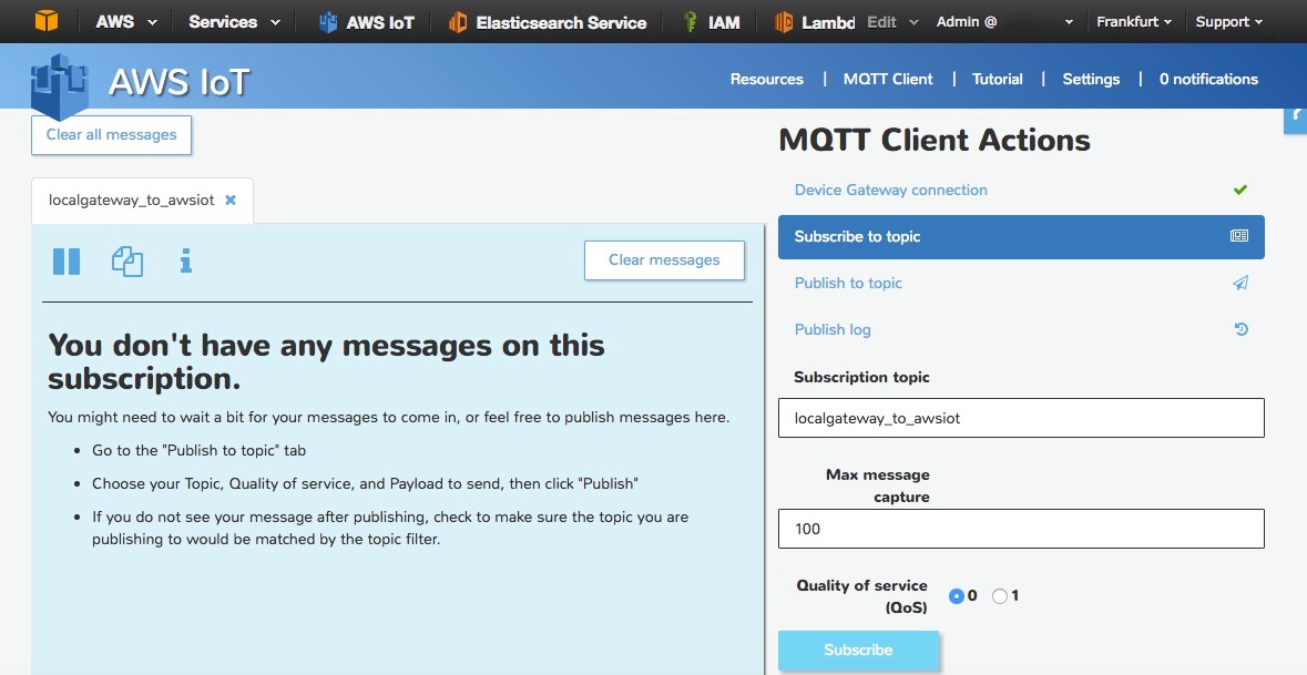
- Go to the AWS IoT Console and click on MQTT Client
- Click on Generate Client Id and Connect
- Click on Subscribe to topic and enter localgateway_to_awsiot, click on Subscribe (Fig. 11)/>
 Now that we have subscribed to this topic on AWS IoT side you can
publish an MQTT message from your terminal (so from the local gateway)
to see if it gets forwarded.
Now that we have subscribed to this topic on AWS IoT side you can
publish an MQTT message from your terminal (so from the local gateway)
to see if it gets forwarded.#Publish a message to the topic
mosquitto_pub -h localhost -p 1883 -q 1 -d -t localgateway_to_awsiot -i clientid1 -m "{\"key\": \"helloFromLocalGateway\"}"
You should now get this message on your screen, delivered by AWS IoT thanks to the bridge.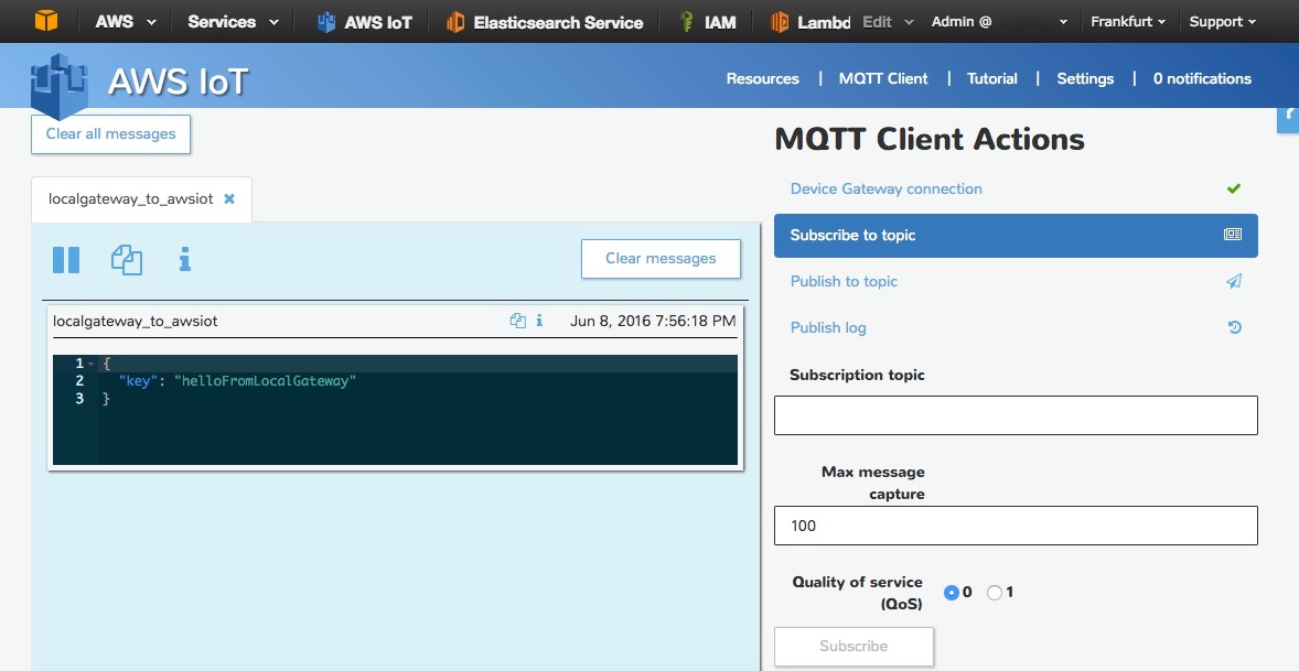
If you are done testing with an Amazon EC2 Instance you can do this with your own local/remote MQTT broker!
Next Steps
The bridge between your local broker and AWS IoT is up and running, you might want to fine tune some parameters of the bridge connection. Please consult the Bridge section of the official Mosquitto documentation if you need additional details.Now that your data is flowing through AWS IoT you can create new IoT applications using other AWS Services for Machine Learning, Analytics, Real-Time Dashboarding and much more so do not hesitate to read our blog, documentation and additional developer resources.
Bites of IoT – Rules Engine and Amazon SNS
In this bite, we will use the AWS IoT rules engine to select and route a message to Amazon Simple Notification Service (Amazon SNS). Specifically, we’ll send a text message to a phone number when someone rings a virtual doorbell.
Concepts Covered in This Bite
The rules engine is often the first point at which your IoT solution can take actions on a device’s messages (for example, message filtering, routing to other services, and even direct processing of messages in your solution).By using AWS IoT and Amazon SNS together, you can send near real-time notifications in response to changes in the physical world as reported by devices in your IoT solution. These notifications can be:
- sent to system operators or technicians for human intervention.
- added to your existing ticketing system.
- used to kick off an automated workflow.
Configure the CLI
As with all Bites of IoT posts, we are using the AWS IoT ELF client available in AWS Labs on GitHub. If you aren’t familiar with the ELF, check out the first post in this series.We’ll use the AWS CLI to create the Amazon SNS topic and AWS IoT rule. In addition to the permissions required by the AWS IoT ELF, you will need to configure the profile used by your CLI with, at minimum, the following permissions. Make sure to replace the value
012345678901 in the policy with your AWS account ID:{
"Version": "2012-10-17",
"Statement": [
{
"Effect": "Allow",
"Action": [
"sns:CreateTopic",
"sns:SetTopicAttributes",
"sns:Subscribe",
"sns:Publish",
"sns:DeleteTopic",
"iot:CreateTopicRule",
"iot:DeleteTopicRule",
"iam:AttachRolePolicy",
"iam:CreatePolicy",
"iam:CreateRole",
"iam:DetachRolePolicy",
"iam:DeletePolicy",
"iam:DeleteRole"
],
"Resource": "*"
},
{
"Effect": "Allow",
"Action": [
"iam:PassRole"
],
"Resource": [
"arn:aws:iam::012345678901:role/*"
]
}
]
}
Create a Bites Directory
If you followed the steps in Getting Started, you should already have a local directory structure of~/dev/aws-iot-elf (where “~” is shorthand for your computer user’s home directory).Each Bite of IoT post will require the creation of local files. Start by creating your Bites directory. On Linux or Mac OS, execute the following commands:
cd ~/dev
mkdir bites
cd ~/dev/bites
Now, in your Bites directory, execute these commands to make a directory for the artifacts used in this post, and then change into that directory.
mkdir sns
cd ~/dev/bites/sns
Now that the basic dev environment is set up, let’s get into the details.
Create the SNS Topic
Create the Amazon SNS topic that the AWS IoT rules engine will be connecting with to send notifications. Use the following AWS CLI commands to create and name the topic. Remember to replace012345678901 in the --topic-arn value with your AWS account ID.aws sns create-topic --region us-west-2 --name door-alert aws sns set-topic-attributes --region us-west-2 --topic-arn arn:aws:sns:us-west-2:012345678901:door-alert --attribute-name DisplayName --attribute-value DOORBELLNote: The
DisplayName value DOORBELL will appear as the “from” address when you receive a notification on your mobile phone.Now subscribe your mobile phone to the topic using the following CLI command. Replace
1-012-345-6789 with your phone number. This command enables your mobile phone to receive the notification when the virtual doorbell rings.aws sns subscribe --region us-west-2 --topic-arn arn:aws:sns:us-west-2:012345678901:door-alert --protocol sms --notification-endpoint 1-012-345-6789You can use this command to validate the subscription:
aws sns publish --region us-west-2 --message "A Bite of Hello" --topic-arn arn:aws:sns:us-west-2:012345678901:door-alert
Create Permissions to Use Amazon SNS
Before we create the IoT rule, we need to create an IAM role that the AWS IoT rules engine will assume and use to securely publish a message to Amazon SNS.The first step to creating the role is to make a trust policy that grants AWS IoT permission to assume the role. Copy and paste the following trust policy document into a temporary file named
iot-role-trust.json:{
"Version":"2012-10-17",
"Statement":[{
"Effect": "Allow",
"Principal": {
"Service": "iot.amazonaws.com"
},
"Action": "sts:AssumeRole"
}]
}
Run the following CLI command to create the role:aws iam create-role --role-name iot_sns_role --assume-role-policy-document file://iot-role-trust.jsonAWS IoT now needs permission to publish to the Amazon SNS topic we created. Copy and paste the following IAM policy document to create a file named
iot-policy.json:{
"Version": "2012-10-17",
"Statement": {
"Effect": "Allow",
"Action": "sns:Publish",
"Resource": "arn:aws:sns:us-west-2:012345678901:door-alert"
}
}
Run the following CLI command to create the policy:aws iam create-policy --policy-name iot_sns_policy --policy-document file://iot-policy.jsonThen run this CLI command to attach the policy to the role:
aws iam attach-role-policy --role-name iot_sns_role --policy-arn arn:aws:iam::012345678901:policy/iot_sns_policy
Create the AWS IoT Rule
Now we can set up the AWS IoT rule that will trigger a text alert when the bell rings. The rule will perform this task by sending every message that comes across the doorbell topic to Amazon SNS. Copy and paste the following rule definition into a file namedsns-rule.json:{
"sql": "SELECT * FROM 'doorbell/+'",
"description": "Sends a message to SNS when a message comes across the 'doorbell' topic",
"actions": [
{
"sns": {
"targetArn":"arn:aws:sns:us-west-2:012345678901:door-alert",
"roleArn":"arn:aws:iam::012345678901:role/iot_sns_role",
"messageFormat": "RAW"
}
}
],
"ruleDisabled": false
}
Remember to replace 012345678901 in the rule with your AWS account ID.Finally, use this CLI command to create the rule:
aws iot create-topic-rule --region us-west-2 --rule-name sendToSNS --topic-rule-payload file://sns-rule.json
Simulate the Doorbell
Everything is now ready to ask the ELF to push the virtual doorbell button. Use the following commands to switch to the AWS IoT ELF directory and get the latest version:cd ~/dev/aws-iot-elf git pullUse this command to activate the ELF’s virtual environment:
source ~/dev/aws-iot-elf/venv/bin/activateOn Windows:
.\venv\Scripts\activateUse this command to create a thing in the AWS IoT service to serve as our doorbell:
python elf.py --region us-west-2 create 1The following command will now send a message on the topic as if the ELF pushed the virtual doorbell button.
python elf.py --region us-west-2 send --duration 1 --topic 'doorbell' 'Somebody is at the door!'Very shortly, your mobile phone should receive a text message similar to this:
DOORBELL> {"msg": "Somebody is at the door!", "ts": "1468958915.41"}
Clean Up
You can use the following commands to clean up your environment:python elf.py --region us-west-2 clean aws iam detach-role-policy --role-name iot_sns_role --policy-arn arn:aws:iam::012345678901:policy/iot_sns_policy aws iam delete-role --role-name iot_sns_role aws iam delete-policy --policy-arn arn:aws:iam::012345678901:policy/iot_sns_policy aws iot delete-topic-rule --region us-west-2 --rule-name sendToSNS aws sns delete-topic --region us-west-2 --topic-arn arn:aws:sns:us-west-2:012345678901:door-alertIf you’d like to clean up the files created in this post, you can remove them from the
~dev/bites/sns directory.Done!
In this bite, you’ve learned how to use AWS IoT and Amazon SNS together to send near real-time notifications in response to messages that come from a thing.We hope you found this walk-through useful. Feel free to leave your feedback in the comments.
Stay tuned for the next post in the Bite of IoT series. Until then, may your success be swift and your solution scalable.
Just-in-Time Registration of Device Certificates on AWS IoT
Using your own certificate with AWS IoT is a two-step process:
- The first step is to register the CA certificate that signed and issued the device certificates.
- After registration, any device certificate that was signed by the CA can be registered with AWS IoT and used for authentication thereafter.
In this blog post, I will explain how JITR works and how it can be used to set up a workflow that activates device certificates and attaches policies to them automatically. I will also walk you through steps for deactivating a CA certificate and revoking device certificates.
You will do the following:
- Create, register, and activate a CA certificate that will be used to sign your device certificate.
- Enable auto-registration of certificates.
- Create device certificates signed by the CA and install them on your device.
- Create and attach a rule with an AWS Lambda action that activates the certificate, and then creates and attaches policies to the certificate.
- Connect to AWS IoT using the device certificate.
In this blog post, I assume you are familiar with AWS IoT and the process of creating an AWS IoT certificate. You will use the AWS CLI and OpenSSL to perform the procedures. If you don’t have the AWS CLI installed, follow these steps. If you already have the AWS CLI, make sure you are using the most recent version.
For information about authentication in AWS IoT or how to use AWS IoT-generated certificates, see the AWS IoT Developer Guide.
Registering Your CA Certificate
If you are a manufacturer, you have purchased CA certificates from vendors like Symantec or Verisign or you have your own CA. To use your own X.509 certificates that have been signed by your CA certificate, AWS IoT must first verify that you not only own the CA certificate, but that you also have access to its private key. The process for validating ownership of a CA certificate is done through a challenge and response workflow.Let’s start by using openssl in a terminal to create your sample CA certificate. In the real world, the signing or intermediate certificates would be issued by your CA vendor. This sample CA certificate is used later in the walkthrough to sign a device certificate that you register with AWS IoT:
$ openssl genrsa -out sampleCACertificate.key 2048
$ openssl req -x509 -new -nodes -key sampleCACertificate.key -sha256 -days 365 -out sampleCACertificate.pem
For simplicity, we are creating and registering the root CA certificate. In reality, the intermediate CA certificate would be signed by the root CA that signs the device certificates. In that case, you register the intermediate CA certificate with AWS IoT.
Now that you’ve created a sample CA certificate, you will register it with AWS IoT. When you register a CA certificate with AWS IoT, you follow a workflow to verify that you have access to both the CA certificate and the private key associated with the CA certificate. To verify ownership of the private key, you generate a verification certificate using the CA certificate, the private key, and a registration code that you generate from AWS IoT.
The registration workflow first requires retrieving the registration code. You can use the AWS CLI or the Register Certificate section in the AWS IoT console to get the registration code.
To use the AWS CLI, run the following command:
$ aws iot get-registration-codeThis command will return a randomly generated, unique registration code that is bound to your AWS account. This registration code is long-lived. It does not expire until you delete it.
Next, you will use the registration code to create a CSR:
$ openssl genrsa -out privateKeyVerification.key 2048
$ openssl req -new -key privateKeyVerification.key -out privateKeyVerification.csr
During the CSR creation process, you will be prompted for information. Enter the registration code into the Common Name field of the verification certificate:
...
Organization Name (eg, company) []:
Organizational Unit Name (eg, section)
Common Name (e.g. server FQDN or YOUR name) []: XXXXXSAMPLEREGISTRATIONCODEXXXXX
EMAIL ADDRESS []:
The registration code establishes that the generated verification certificate was created specifically for registering the CA certificate with AWS IoT, and that the verification certificate is not a previously issued certificate.
Now that you have a CSR that includes the registration code, use your first sample CA certificate and the CSR to create a new certificate:
$ openssl x509 -req -in privateKeyVerification.csr -CA sampleCACertificate.pem -CAkey sampleCACertificate.key -CAcreateserial -out privateKeyVerification.crt -days 365 -sha256When you register your CA certificate with AWS IoT, the combination of the registration code, verification certificate signed with the CA private key, and the CA certificate are used to verify ownership of the CA private key.
Next, you will use the verification certificate to register your sample CA certificate:
$ aws iot register-ca-certificate --ca-certificate file://sampleCACertificate.pem --verification-certificate file://privateKeyVerification.crtYou can make a describe-ca-certificate call to get the information on the registered CA certificate. You will use the certificate ID of the registered CA returned in the response of the previous CLI command.
$ aws iot describe-ca-certificate --certificate-id <certificateId>Next, you will activate the CA certificate. By default, the CA certificate will be registered in an INACTIVE state. At the time of the registration of the device certificate, AWS IoT will consult the status of its registered CA certificate and will allow the registration of the device certificate only if the CA certificate is in an ACTIVE state. Use the update-ca-certificate CLI command to change the status of the CA certificate. Alternatively, you can register the CA certificate in the ACTIVE state by passing the set-as-active flag at the time of registration:
$ aws iot update-ca-certificate --certificate-id <certificateId> --new-status ACTIVEBy default, the auto-registration-status of the registered CA certificate is disabled. That means any device certificate issued by the registered CA will not be auto-registered by default when it first connects to the AWS IoT service. However, you can use the register-certificate CLI command to explicitly register the device certificate. If the auto-registration-status is enabled for a CA certificate, the device certificate issued by that CA will be auto-registered, if not already registered, when it connects to AWS IoT for the first time. To opt in for the auto-registration of the device certificates issued by a registered CA, set the auto-registration-status for the CA certificate to ENABLE.
You can enable the auto-registration-status through the update-ca-certificate CLI command. Alternatively, you can register the CA certificate with the auto-registration-status enabled by passing the --allow-auto-registration flag to the register-ca-certificate CLI command.
$ aws iot update-ca-certificate --certificate-id <caCertificateId> --new-auto-registration-status ENABLE
Device Certificate Registration Event and Action
When a device attempts to connect with an X.509 certificate that is not known to AWS IoT but was signed by a CA that was registered with AWS IoT, the device certificate will be auto-registered by AWS IoT in a new PENDING_ACTIVATION state. PENDING_ACTIVATION means that the device certificate was auto-registered and is awaiting activation. Only AWS IoT can mark the status of a certificate as PENDING_ACTIVATION. If you connect with a certificate in PENDING_ACTIVATION state, a TLS handshake failure will occur because only ACTIVE certificates are authenticated with AWS IoT. For this reason, you need to change the status of the registered certificate from PENDING_ACTIVATION to ACTIVE so that it can be successfully authenticated.When AWS IoT auto-registers a certificate or when a certificate in PENDING_ACTIVATION status connects, it publishes a message to the following MQTT topic:
$aws/events/certificates/registered/<caCertificateID>where the caCertificateId is the ID of the CA certificate that issued the device certificate.
The message published to this topic has the following structure:
{
  "certificateId": "<certificateID>",
  "caCertificateId": "<caCertificateId>",
  "timestamp": "<timestamp>",
  "certificateStatus": "PENDING_ACTIVATION",
  "awsAccountId": "<awsAccountId>",
  "certificateRegistrationTimestamp": "<certificateRegistrationTimestamp>"
}
You can subscribe or attach any AWS IoT rule to the
registration topic. The attached AWS IoT rules can then take some action
based on the messages received. For example, an AWS IoT rule in your
account can listen on the $aws/events/certificates/registered/+ topic to
build an Amazon DynamoDB table of all the registered certificates. The general recommendation is to attach an AWS IoT rules engine action to the registration topic that will perform the bootstrapping or provisioning steps (like consulting your CRLs) and then activate/deactivate/revoke the certificate, create and attach the policies to the certificate, and so on.In the following example, we will create a topic rule with an AWS Lambda action on the registration topic that will activate the certificate and create and attach a policy.
Use the AWS Lambda console to create the AWS Lambda function:
- Sign in to the AWS Management Console and open the AWS Lambda console at https://console.aws.amazon.com/lambda/home?region=us-east-1.
- Choose Create an AWS Lambda function.
- On the Configure function page, type a name and description for the AWS Lambda function. In Runtime, choose Node.js 4.3.
- Scroll down to the AWS Lambda function code section of the page. Replace the existing code with this sample code.
- Scroll down to the AWS Lambda function handler and role section of the page. For Role, choose Create a custom role. When the IAM console opens, you can create an IAM role that AWS Lambda can assume when executing the AWS Lambda function.
- In the navigation pane, choose Create New Role.
- For Role name, type a role name.To edit the role’s policy to give it permission to update the certificate and create and attach the policy:
- Choose View Policy Document.
- Replace the policy document with the following:
{ "Version":"2012-10-17", "Statement":[ { "Effect":"Allow", "Action":[ "logs:CreateLogGroup", "logs:CreateLogStream", "logs:PutLogEvents" ], "Resource":"arn:aws:logs:*:*:*" }, { "Effect":"Allow", "Action":[ "iot:UpdateCertificate", "iot:CreatePolicy", "iot:AttachPrincipalPolicy" ], "Resource":"*" } ] } - Choose Allow.
- Leave the settings on the Advanced settings page at their defaults, and choose Next.
- On the Review page, choose Create function.
Creating an AWS Lambda Rule
Now that you have created an AWS Lambda function, you can create a rule that invokes the function.- In the AWS IoT console, choose Create a resource.
- Choose Create a rule.
- Type a name and description for the rule.
- Enter the following settings for the rule:
SQL version: 2016-03-23-beta
Attribute: *
Topic filter: $aws/events/certificates/registered/<caCertificateID> Note: Replace <caCertificateId> with the ID of the registered CA certificate. - For Choose an action, choose Insert this message into a code function and execute it (AWS Lambda).
- From Function name, choose your AWS Lambda function name, and then choose Add action.
- Choose Create to create your AWS Lambda function.
Note: If you created the rule through the AWS IoT console, you can skip this step. The console does this for you when you create the AWS Lambda rule.
You will use the AWS Lambda AddPermission API to grant permissions:
aws lambda add-permission --function-name <lambda-function-name> --region us-east-1 --principal iot.amazonaws.com --source-arn <rule-arn> --source-account <your-aws-account> --statement-id Id-123 --action "lambda:InvokeFunction"
Auto-registration of a Device Certificate Signed by Your CA Certificate
Now that you’ve created, registered, and activated a sample CA certificate with auto-registration-status enabled and configured a rule with an AWS Lambda action to activate the certificate and attach policies, use the CA certificate to create a new device certificate and auto-register it when it first connects to AWS IoT.Enter the following commands in your terminal to create a device certificate:
$ openssl genrsa -out deviceCert.key 2048
$ openssl req -new -key deviceCert.key -out deviceCert.csr
$ openssl x509 -req -in deviceCert.csr -CA sampleCACertificate.pem -CAkey sampleCACertificate.key -CAcreateserial -out deviceCert.crt -days 365 -sha256
Next, try to connect to AWS IoT using the device certificate. Because you’ve completed the preceding steps, your device certificates will be auto-registered during the TLS handshake when it connects to AWS IoT for the first time. At the time of connection, you need to send both the device certificate and its registered CA certificate.
Create a certificate file that contains the device certificate and its registered CA certificate. Here is the Linux command:
$ cat deviceCert.crt sampleCACertificate.pem > deviceCertAndCACert.crtIn the following example, you will use the MQTT Mosquitto client to connect and publish to AWS IoT using the device certificate:
$ mosquitto_pub --cafile root.cert --cert deviceCertAndCACert.crt --key deviceCert.key -h <prefix>.iot.us-east-1.amazonaws.com -p 8883 -q 1 -t foo/bar -i anyclientID --tls-version tlsv1.2 -m "Hello" -dNote: The root.cert is the AWS IoT root certificate. The AWS IoT root CA certificate is used by a device to verify the identity of the AWS IoT servers. Click here to download the root certificate. Save this file to your desktop and name it “root.cert”.
You will see a TLS failure when you run the command because AWS IoT disconnects the connection after the registration of the device certificate. AWS IoT has registered the certificate in the PENDING_ACTIVATION state and won’t let it connect and authenticate unless the certificate is marked ACTIVE. The client or device should implement an automatic reconnect strategy when it is disconnected due to the TLS error. The device should also implement a back-off strategy (that is, increase the time between retries) to avoid unnecessary network traffic and allow your own activation logic to complete before devices attempt to reconnect.
The commands to connect to AWS IoT with the device certificate whose CA has been registered will lead to the auto-registration of the device certificate during the TLS handshake. An MQTT registration event will be published on the registration topic and trigger the attached Lambda rule action to activate the certificate and attach the policy to it. This will complete the registration and provisioning of the device certificate. It can now be used for authentication and authorization with AWS IoT. After a device certificate is registered with AWS IoT, you can interact with it in a way that’s similar to a device certificate generated by AWS IoT. You can activate/deactivate /revoke certificates, attach policies, and associate things to your device certificates. In addition, you can manage the lifecycle of that device certificate in AWS IoT by deactivating, revoking, or activating the certificate in your AWS account.
Deactivate the CA Certificate
During device certificate registration, AWS IoT will check if the associated CA certificate is active. If the CA certificate is inactive, AWS IoT will not allow the device certificate to be registered. This feature provides you with the flexibility to manage the lifecycle of device certificates signed by the registered CA that are yet to be registered with AWS IoT. By marking the status INACTIVE, you prevent any new device certificates issued by the compromised CA to be registered in your account. You can run the following command to deactivate the CA certificate:$ aws iot update-ca-certificate --certificate-id <certificateId> --new-status INACTIVENote: Running this command will not deactivate all of your registered device certificates. It will prevent new device certificates from being registered.
Revoke the Device Certificate
If you wish to revoke a registered device certificate, use the following command to revoke it:$ aws iot update-certificate --certificate-id <certificateId> --new-status REVOKEDUse the list-certificates-by-ca CLI command to get a list of registered device certificates, sorted by the date of registration, that are issued by the CA certificate:
$ aws iot list-certificates-by-ca --ca-certificate-id <caCertificateId>If an error or exception occurs during the auto-registration of the device certificates, AWS IoT will send the events or message to CloudWatch Logs. To set up CloudWatch Logs for your account, see the AWS IoT Developer Guide.
Conclusion
We hope you found these steps (using your own device certificate with AWS IoT, auto-registration of device certificates, and deactivating CA certificates) useful and will use them to provision and register your device certificates with AWS IoT. Give it a try and feel free to leave your feedback in the comments.Bites of IoT – Introduction
In this first bite, we’ll set up a very simple client that can create things in AWS IoT, send messages to those things, subscribe to topics to receive messages from things, and then clean up. The client is available through AWS Labs on GitHub. It’s used in this post to illustrate some IoT concepts, but will be used in later posts in this series, too.
Before we get into the details, let’s cover a few concepts:
AWS IoT is a managed service in the AWS Cloud that enables your devices to easily and securely connect to a rich ecosystem of cloud-based services or your own homegrown systems. The service enables this connectivity while reliably scaling to billions of devices sending trillions of messages. The service includes these building blocks:
Message Broker – Acts as a front door for your device to the AWS Cloud. The message broker exposes publish-and-subscribe messaging capabilities available for use by devices through transport protocols like MQTT, HTTP, and WebSocket.
Rules Engine – This is the point closest to the front door where your solution can make decisions about a device’s messages (for example, message filtering, routing messages to other services, and even a direct processing of messages in your solution). We will explore the facets of the rules engine in later posts.
Device Shadow – Sometimes referred to as a thing shadow, this is a logical representation of a physical device’s reported state or desired future state. Although the concept is a bit abstract, this building block provides a huge benefit for customers who build web- or mobile-based applications that need to interact with real devices at any scale. In later posts, we will explore the ways in which the device shadow is used in these interactions.
AWS APIs and the AWS Management Console – These are the mechanisms used to provision every AWS service. This post and all others in this series will include interaction with AWS through the APIs and AWS Management Console. In all Bites of IoT posts we assume you have an IAM user with developer-level permissions in an AWS account.
The relationships between these building blocks is:
AWS IoT has a message broker, rules engine, and device shadows.
AWS IoT is a part of the AWS Cloud.
AWS IoT is a part of the AWS Cloud.
Installing ELF
The AWS IoT ELF Python example client demonstrates how you can create things, send messages to things, subscribe to topics to receive messages from things, and clean up things in AWS IoT by using the AWS SDK for Python and the standard AWS IoT device client.To ensure you have a simple working IoT client for this and subsequent blog posts, follow the Getting Started instructions for your computing environment. Make sure your AWS user can access the AWS IoT console.
Understanding the ELF Client and AWS IoT
We’ll go through the AWS IoT ELF commands to show how a device interacts with the building blocks of AWS IoT.When you execute the
create command, AWS IoT
ELF will create a certificate, then a thing, and then attach the thing
to the certificate. At this point, the device that possesses the
certificate (in this case, IoT ELF) can use the AWS IoT service as if it
actually is the logical thing.Like a driver’s license that identifies a person and conveys the privilege to drive, a certificate identifies the thing and conveys the privilege to use the thing’s AWS IoT building blocks; specifically, the device can interact with the device shadow and message broker.
When you execute the send command, AWS IoT ELF will first create a policy that allows interaction with thing-specific topics for general messaging and device shadow messages. Then AWS IoT ELF will attach the policy to the certificate. The device can now publish and subscribe to messages on topics in the message broker and interact with the device shadow associated with the previously attached thing.
To continue the driver’s license analogy, even after drivers obtain a license, they can only use their car on roads in the country for which they have the privilege to drive. Similarly, when a device has a certificate, it can interact with the AWS IoT service, but the IoT policy dictates which topics or “lanes” the device can use to send and receive messages.
After a policy is configured for a device (or, in this case, AWS IoT ELF) the topics through which messages are sent convey the purpose of each message to a customer’s solution.
For example, messages sent or received on a topic
elf/thing_0 are considered general purpose messages for the ELF
in the solution. These messages might have a customer-defined format
and convey telemetry or commands for use by the customer’s solution. But
there are topics in AWS IoT that are reserved for interaction with
building blocks of the AWS IoT service itself.For example, a device named
thing_0 can report
its current state and subscribe to requests to change state through
messages flowing through the thing’s device shadow topic $aws/things/thing_0/shadow/update.
Messages sent and received on this topic must follow the format
expected by the device shadow and are tracked as state transitions of
the thing.This topic-based interaction keeps messages flowing in the correct lanes of the solution. It is controlled by using AWS IoT to attach policies to the certificate possessed by the device.
Finally, when you execute the
clean command,
AWS IoT ELF detaches the IoT policy and thing from the certificate,
deactivates the certificate, and then deletes the policy, thing, and
certificate.Subscribing to Topics in the AWS Console
Instead of using thesubscribe command in AWS
IoT ELF, we will now use the ELF to send messages to AWS IoT and then
use the AWS IoT console to subscribe to those messages:- Sign in to the AWS Management Console, and then choose the AWS IoT icon.
- In the AWS IoT console, choose MQTT Client.
- In the Client ID field, type
web-elf, and then choose Connect. - Choose Subscribe to topic and in the Subscription topic field, type
elf/#. This will subscribe the console’s built-in MQTT client to the default AWS IoT ELF topic.
Execute these commands from the directory in which you installed AWS IoT ELF:
python elf.py create
python elf.py send --duration 30
Go back the AWS IoT console, and for about 30 seconds, you will see messages being sent by AWS IoT ELF.
Specifically, what you’re seeing in the console is a result of:
- The ELF creating messages to send.
- The ELF sharing the certificate with AWS IoT to identify itself as a device mapped to a thing.
- The ELF using the MQTT protocol to send a message to the
elf/thing_0topic. - The policy previously attached to the certificate being checked and, if the policy allows it, the message being sent on the
elf/thing_0topic. - The AWS IoT console’s built-in MQTT client indirectly subscribing to the
elf/thing_0topic. (The#inelf/#is a wildcard that means “everything from this point in the topic hierarchy and below.”)
Next Topics in the Series
Upcoming Bites of IoT posts will show simple routing examples using AWS IoT ELF and the rules engine. These examples will cover sending notifications, streaming and saving messages, republishing messages, computing on messages, and finally, searching messages.After that, we’ll explore the not-so-shadowy world of device shadows to show how truly powerful this building block can be when added to an IoT solution designer’s toolbox.
I hope you’ve enjoyed taking your first small bite out of IoT. I look forward to offering up other tasty morsels in the near future.
May your success be swift and your solution scalable. Feel free to leave your feedback in the comments.
Anomaly Detection Using AWS IoT and AWS Lambda
In this blog post, we will focus on detecting contextual anomalies. An example of a contextual anomaly is a temperature measurement that suddenly jumps from 50 to 70 degrees. The 70-degree measurement may not be unusual, but it is unusual in a context in which previous measurements were much lower. For more information about anomaly detection, see the survey by Varun Chandola, et al. [1]
Prerequisites
You should be familiar with the AWS CLI and should have set up an Amazon Cognito identity pool. For information, see Authenticate Users with Amazon Cognito Identity.Although mathematical knowledge is not required, we encourage you to check out the references.
Contextual Anomaly Detection
The demo in this post uses wind velocity measurements from the San Francisco Wind Monitoring Data as the data set. You can download the formatted data set here. The algorithm we’ll use is called the probabilistic exponentially weighted moving average (PEWMA), which was proposed by Carter and Streilein [2]. The details of the algorithm are not covered in this post, but at a high level, the algorithm is calculating an average and standard deviation of the time-series data and evaluating the probability of observing the current point. If the probability is below a set threshold, then it is marked as an anomaly. A plot of the raw data and an example of the upper and lower bounds of what is considered to be normal behavior is shown here: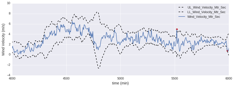
The data flow for this anomaly detection process is shown in the following figure:
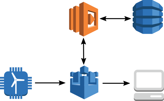
Data is sent from our sensor to AWS IoT, where it is routed to AWS Lambda through the AWS IoT Rules Engine. Lambda executes the logic for anomaly detection and because the algorithm requires knowledge of previous measurements, uses Amazon DynamoDB as a key-value store. The Lambda function republishes the message along with parameters extracted from the PEWMA algorithm. The results can be viewed in your browser through a WebSocket connection to AWS IoT on your local machine. A variation of this flow is to route observations marked as anomalous to Amazon Elasticsearch Service (Amazon ES) or Amazon S3.
For the anomaly detection method, we are using AWS Lambda with Python 2.7. Use the following AWS CLI command to set up your DynamoDB table:
aws dynamodb create-table --table-name windDemo --attribute-definitions AttributeName=Station_Name,AttributeType=S --key-schema AttributeName=Station_Name,KeyType=HASH --provisioned-throughput ReadCapacityUnits=50,WriteCapacityUnits=50Now we need to create a role that will give trust permissions to Lambda and AWS IoT to execute actions on our behalf. To do this, save the following text as iot_lambda_role.json.
{
"Version": "2012-10-17",
"Statement": [{
   "Sid": "",
   "Effect": "Allow",
   "Principal": {
      "Service": ["lambda.amazonaws.com", "iot.amazonaws.com"]
   },
   "Action": "sts:AssumeRole"
 }]
}
The actions Lambda will execute on our behalf (access
DynamoDB, AWS IoT, and logging) are defined in a policy document like
the following. Save the following text as anom_det_policy.json.{
"Version": "2012-10-17",
"Statement": [
{
"Sid": "Stmt1463425014235",
"Action": [
"dynamodb:GetItem",
"dynamodb:PutItem"
],
"Effect": "Allow",
"Resource": "*"
},
{
"Sid": "Stmt1463425053236",
"Action": [
"iot:Connect",
"iot:Publish"
],
"Effect": "Allow",
"Resource": "*"
},
{
"Effect": "Allow",
"Action": [
"logs:CreateLogGroup",
"logs:CreateLogStream",
"logs:PutLogEvents"
],
"Resource": "arn:aws:logs:*:*:*"
}
]
}
The following commands will create the role, create the policy, and attach the policy to the role.aws iam create-role --role-name iot_lambda_role --assume-role-policy-document file://iot_lambda_role.json aws iam create-policy --policy-name anom_det_policy --policy-document file://anom_det_policy.json aws iam attach-role-policy --role-name iot_lambda_role --policy-arn arn:aws:iam::<your-aws-account-id-here>:policy/anom_det_policyThe next step is to create the Lambda function. Download the code for the Lambda function. The Lambda function will be executed every time a message is sent to the anom/detect topic. It will perform the PEWMA algorithm and republish the results to the anom/pred topic. Use the following command to create the Lambda function from the AWS CLI.
aws lambda create-function \
 --function-name anom_detector \
 --runtime python2.7 \
 --region us-east-1 \
 --role arn:aws:iam::<your-aws-account-id-here>:role/iot_lambda_role  \
 --handler lambda_function.lambda_handler \
 --memory-size 512 \
 --timeout 15 \
 --description "lambda function which implements probabilistic exponentially weighted moving average" \
 --zip-file fileb://lambda_function.zip
Now we need to create a rule that will send messages on a topic in AWS IoT to the Lambda function and give our rule permission to invoke Lambda. Copy and paste the following code into a JSON file and save it as anomaly_rule.json.
{
        "sql": "SELECT * FROM 'anom/detect'",
        "ruleDisabled": false,
        "actions": [{
          "lambda": {
            "functionArn": "arn:aws:lambda:us-east-1:<your-aws-account-id-here>:function:anom_detector"
           }
         }]
}
We will use this JSON message to create the rule and give it permission to call Lambda using the following AWS CLI commands.aws iot create-topic-rule --rule-name anomaly_detection_lambda --topic-rule-payload file://anomaly_rule.json aws lambda add-permission --function-name "anom_detector" --region "us-east-1" --principal iot.amazonaws.com --source-arn arn:aws:iot:us-east-1:<your-aws-account-id-here>:rule/anomaly_detection_lambda --source-account "<your-aws-account-id-here>" --statement-id "123123123" --action "lambda:InvokeFunction"All of the resources required to run the demo are now created. To run the demo, download this script, and then use the following AWS CLI command to start sending data to AWS IoT.
python emit_json_data.py anom/detect SF36.json
Viewing Your Data Stream and Anomaly Boundaries
To connect to AWS IoT and view the output of the anomaly detection algorithm, download this WebSocket example. To use the websocket demo on your local machine, modify the config.js file to include your access key, secret key, Amazon Cognito pool ID, region, and AWS IoT endpoint. This websocket demo is only meant to be run on your local machine to be able to visualize the data stream and anomaly boundaries. Do not publish the html page in the demo to the public or in general any code that contains your API or secret key. If you don’t know your IoT endpoint, use the following AWS CLI command.aws iot describe-endpointNow you can open the index.html file, connect to AWS IoT, and subscribe to the topic the anomaly detection algorithm is publishing to. You should start to see the plot of the raw data and the calculation of the anomaly boundaries. The anomaly boundaries set for the plot are 3.3 standard deviations away from the moving average, which corresponds to a threshold of 0.002. After the streaming plot is working, you can modify the alpha_0 and beta parameters in the Lambda function to see how those changes affect the anomaly boundary in real time.
The following figures shows what the streaming anomaly plot should look like in your browser:
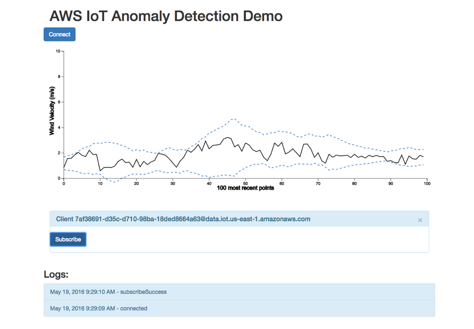
Conclusion
This demo in this post has shown you how to perform anomaly detection for sensor data on a thing connected to AWS IoT. This approach could scale to many things. You can use a unique identifier for each sensor you want to monitor as a hash key in DynamoDB. A useful extension for this process would be to add a WHERE statement to the rule on anom/pred that filters the data so that only anomalous observations are routed to Amazon S3 or Amazon ES for analysis. We would love to hear your feedback!Appendix: Tuning the PEWMA Algorithm to Your Data
The Lambda function has four parameters that you can change to tune the behavior of the algorithm. Two of these parameters are used to select pieces of the JSON messages and identify a DynamoDB table to use to persist state information for the algorithm. If you want to generalize the approach in this demo to work on a different data set, you will need to change a few parameters, including the name of the DynamoDB table (table_name) and and the JSON object (data_cols). You may also want to tweak alpha_0, beta, and threshold until the algorithm is identifying what you believe are anomalies.alpha_0 This parameter is used to specify how much weight to give to the previous value of the mean in determining the moving average. The default value is 0.95. The closer this parameter is to 1, the smoother the moving average will be. The closer this parameter is to 0, the more quickly the moving average will adjust to changing patterns in the data.
beta This parameter ranges from 0 to 1. It prevents anomalies from strongly shifting the mean. The larger the value, the more we limit the effect an anomalous point has on the mean. In the demo, we use a default of 0.5.
data_cols The object of our AWS IoT JSON payload where we want to perform anomaly detection.
key_param The object of our AWS IoT JSON payload to be used as the hash key in our DynamoDB table. Usually a device ID.
T The number of points to use to calculate the initial value for the moving average. The default value is 30.
table_name The name of the DynamoDB table used to persist data required during the execution of the PEWMA algorithm.
threshold This parameter sets the limit for what we call an anomaly. The lower the value, the fewer points will be classified as anomalies.
The following plots illustrate the effect that some of the parameters have on the PEWMA algorithm.
threshold
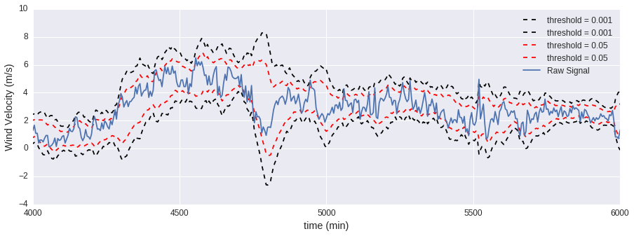
Raising the threshold reduces the area that is considered normal.
alpha_0
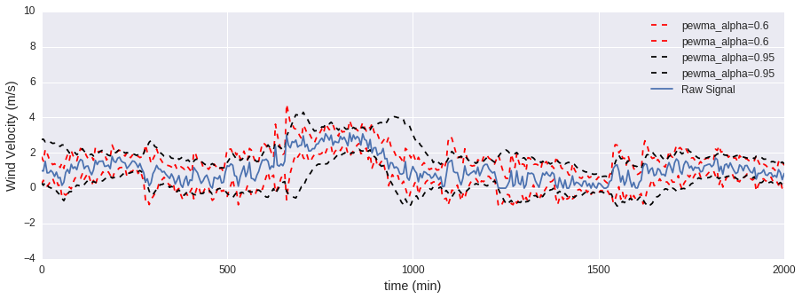
You can think of alpha_0 as a smoothing parameter. The closer this parameter is to 1, the smoother the moving average will be.
beta
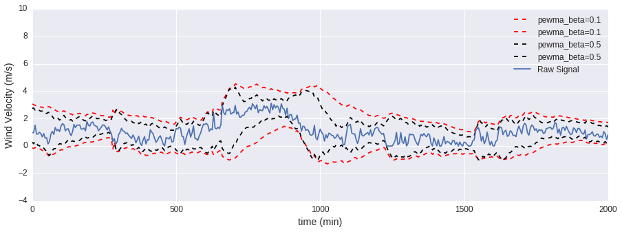
The closer this parameter is to 1, the more the effect of anomalies on the moving average and standard deviation is minimized. To perform a standard exponentially weighted moving average, set this parameter to 0.
References
[1] Chandola, Varun, Arindam Banerjee, and Vipin Kumar. “Anomaly detection: A survey.” ACM computing surveys (CSUR) 41.3 (2009): 15.[2] Carter, Kevin M., and William W. Streilein. “Probabilistic reasoning for streaming anomaly detection.” Statistical Signal Processing Workshop (SSP), 2012 IEEE. IEEE, 2012.
=---> .
|
https://aws.amazon.com/blogs/iot/
http://www.rcrwireless.com/20160906/telco-cloud/iot-cloud-providers-tag31-tag99